94 Rockwell Automation Publication 20P-TG002B-EN-P - February 2018
Chapter 3 Part Replacement Procedures
• Use the following table to determine the proper tightening torque for
the bus bars connected to the SCR modules:
Bimetal Thermostats
Replacement
Remove the Bimetal Thermostats
Follow these steps to remove the bimetal thermostats.
1. Read the General Safety Precautions on page 10
.
2. Remove power from the drive (see page 42
).
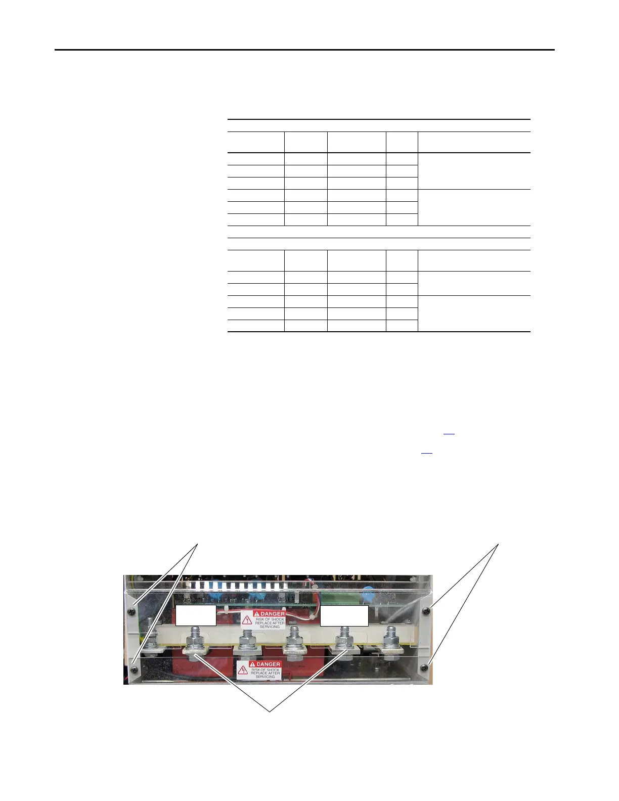
3. Remove the screws and washers that secure the plastic shields to the
bottom of the drive and remove the shields.
4. Remove the bolts, washers and wiring from the U phase AC input
power terminal and the D power terminal.
230V AC Input
Drive Current
Rating Code
DC Amps AC Line Amps Hp Final Torque
146 146 119 40 4.5…5.5 N
•m (40…48.7 lb•in)
180 180 147 50
218 218 178 60
265 265 217 75 11…13 N
•m (97.4…115 lb•in)
360 360 294 100
434 434 355 125
460V AC Input
Drive Current
Rating Code
DC Amps AC Line Amps Hp Final Torque
167 167 136.4 100 4.5…5.5 N
•m (40…48.7 lb•in)
207 207 169.1 125
250 250 204.3 150 11…13 N
•m (97.4…115 lb•in)
330 330 269.6 200
412 412 336.6 250
3
3
U Phase
4
Bottom View of Drive
D Terminal

 Loading...


