EasyManuals Logo

Rockwell Automation Allen-Bradley PowerFlex 20P Hardware Service Manual

Rockwell Automation Allen-Bradley PowerFlex 20P
130 pages
To Next Page IconTo Next Page
To Previous Page IconTo Previous Page
Page #51 background imageLoading...
Page #51 background image
Rockwell Automation Publication 20P-TG002B-EN-P - February 2018 51
Part Replacement Procedures Chapter 3
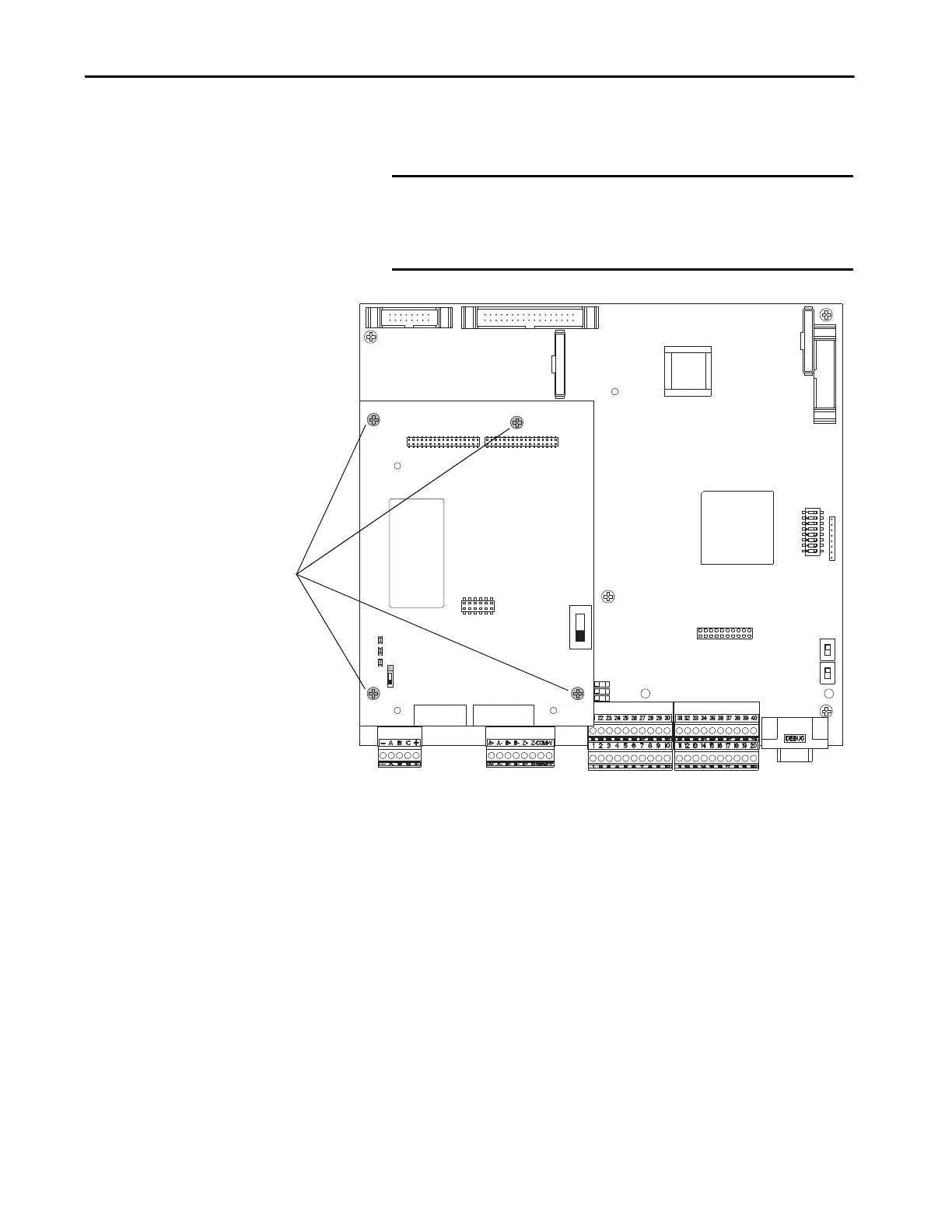
7. Remove the four hexalobular screws that secure the resolver interface
board to the control board and remove the resolver interface board.
Install the Resolver Feedback and Interface Circuit Boards
Install the resolver feedback and interface boards in reverse order of removal.
IMPORTANT The resolver interface board is connected to the control board below
it via a stacker connector pin at connector XRE. Lift the resolver
interface board straight up during removal to avoid any damage to
the connector pin.
S15
XR
XA
XP3
XRE
XFCD
S21
S4
P2 P3
S1
TB1 TB2
XRE
S2
7
Tightening torque for re-
assembly is
0.7 Nm (6.2 lbin)

Table of Contents

Other manuals for Rockwell Automation Allen-Bradley PowerFlex 20P

Questions and Answers:

Question and Answer IconNeed help?

Do you have a question about the Rockwell Automation Allen-Bradley PowerFlex 20P and is the answer not in the manual?

Rockwell Automation Allen-Bradley PowerFlex 20P Specifications

General IconGeneral
BrandRockwell Automation
ModelAllen-Bradley PowerFlex 20P
CategoryDC Drives
LanguageEnglish

Related product manuals