32 Rockwell Automation Publication 20P-TG002B-EN-P - February 2018
Chapter 2 Component Test Procedures
Check the Field SCR/Dual Diode Module
The field supply consists of a dual pack SCR/dual diode module arranged in a
single–phase full wave rectifier configuration. Malfunction of either of these
components may cause various responses including field and velocity related
faults, or blown fuses. The following procedures can be used if field bridge
malfunctions are suspected.
1. Read the General Safety Precautions on page 10
.
2. Remove and lock-out all incoming power to the drive (see page 42).
3. Remove the protective covers (see page 43
).
4. Verify that contactor power (if used) is removed.
5. Verify that power to an external field supply (if used) is removed.
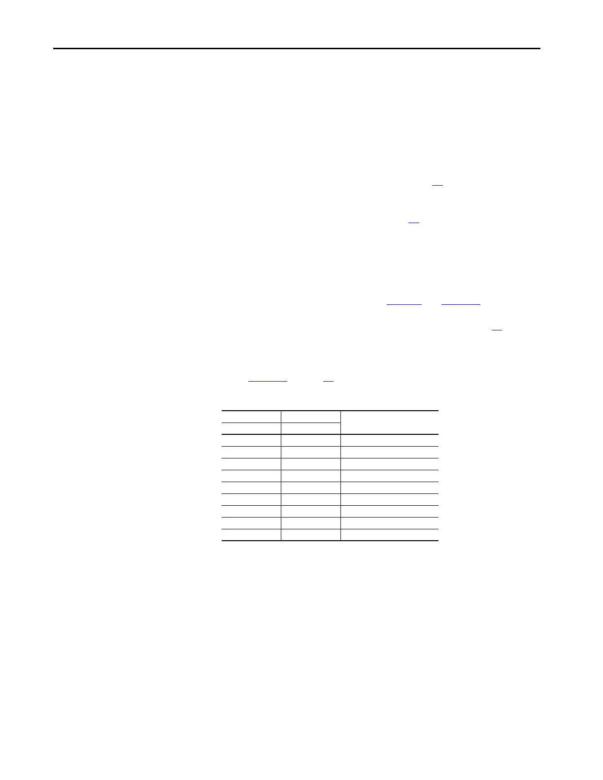
6. Check the anode to cathode junction of the field SCR/dual diode
module. With the digital multimeter set to “diode test”, measure the
resistance across the modules. See Table 1 0
and Figure 10.
If a low resistance is detected, replace the modules (see page 77
).
If a measurement results in an “infinity” reading, check the fuses at FU1
and FV1 on the control panel to determine if they are open. See
Figure 11
on page 33.
Table 10 - Field SCR/Dual Diode Module Anode to Cathode Junction Measurements
(+) Meter Lead (-) Meter Lead Nominal Meter Reading
Terminal Terminal
U1 C1 “open” or ∞
U1 D1 “open” or ∞
V1 C1 “open” or ∞
V1 D1 “open” or ∞
C1 D1 “open” or ∞
C1 U1 “open” or ∞
C1 V1 0.50V
D1 C1 0.50V
D1 U1 0.45V

 Loading...


