Rockwell Automation Publication 20P-TG002B-EN-P - February 2018 69
Part Replacement Procedures Chapter 3
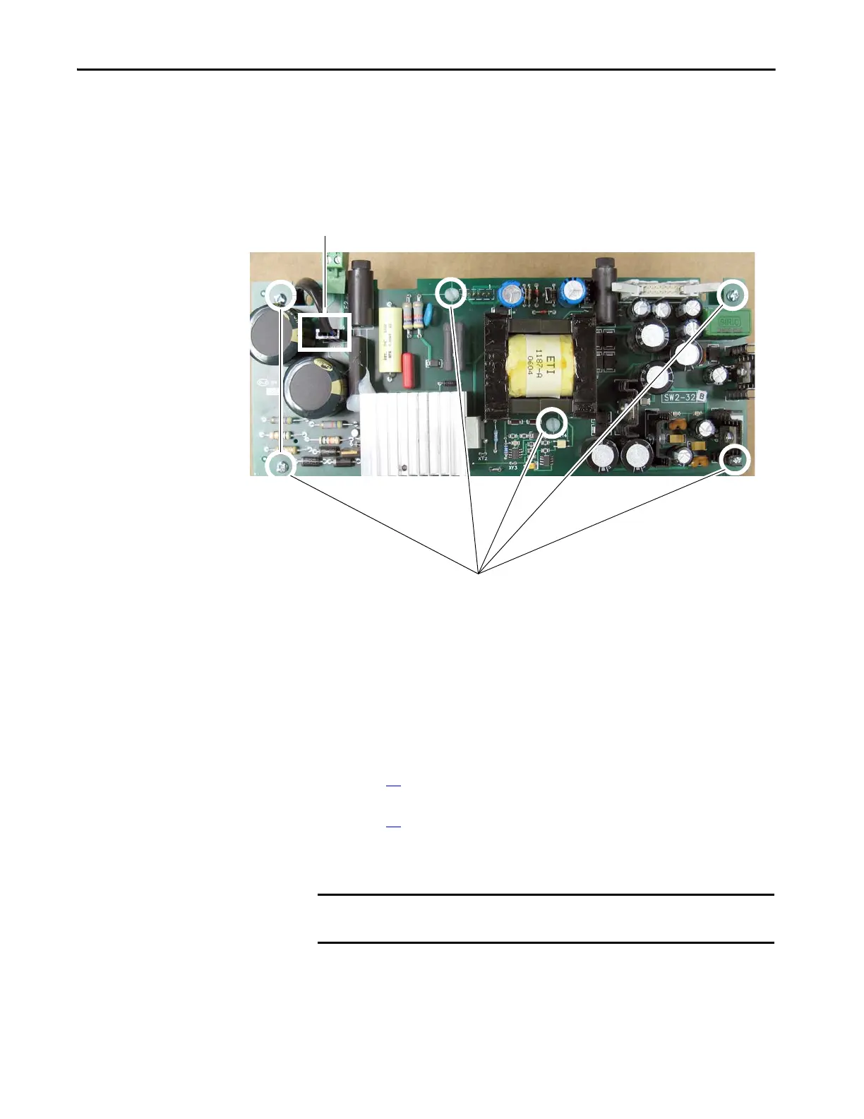
16. Remove the cable from connector XUV on the switching power supply
board.
17. Remove the six screws and washers that secure the switching power
supply board to the stand-offs on the back of the pulse transformer
board and remove the switching power supply board.
Configure the Pulse Transformer Circuit Board
The steps required to configure the pulse transformer board are different based
on the revision code of the pulse transformer board. See one of these
procedures:
• Configure a Pulse Transformer Board FIR2-xx Rev. “M” and Lower on
page 69
• Configure a Pulse Transformer Board FIR2-xx Rev. “N” and Higher on
page 72
Configure a Pulse Transformer Board FIR2-xx Rev. “M” and Lower
IMPORTANT This procedure requires a multimeter that measures resistance to
thousandths of an ohm.

 Loading...


