80 Rockwell Automation Publication 20P-TG002B-EN-P - February 2018
Chapter 3 Part Replacement Procedures
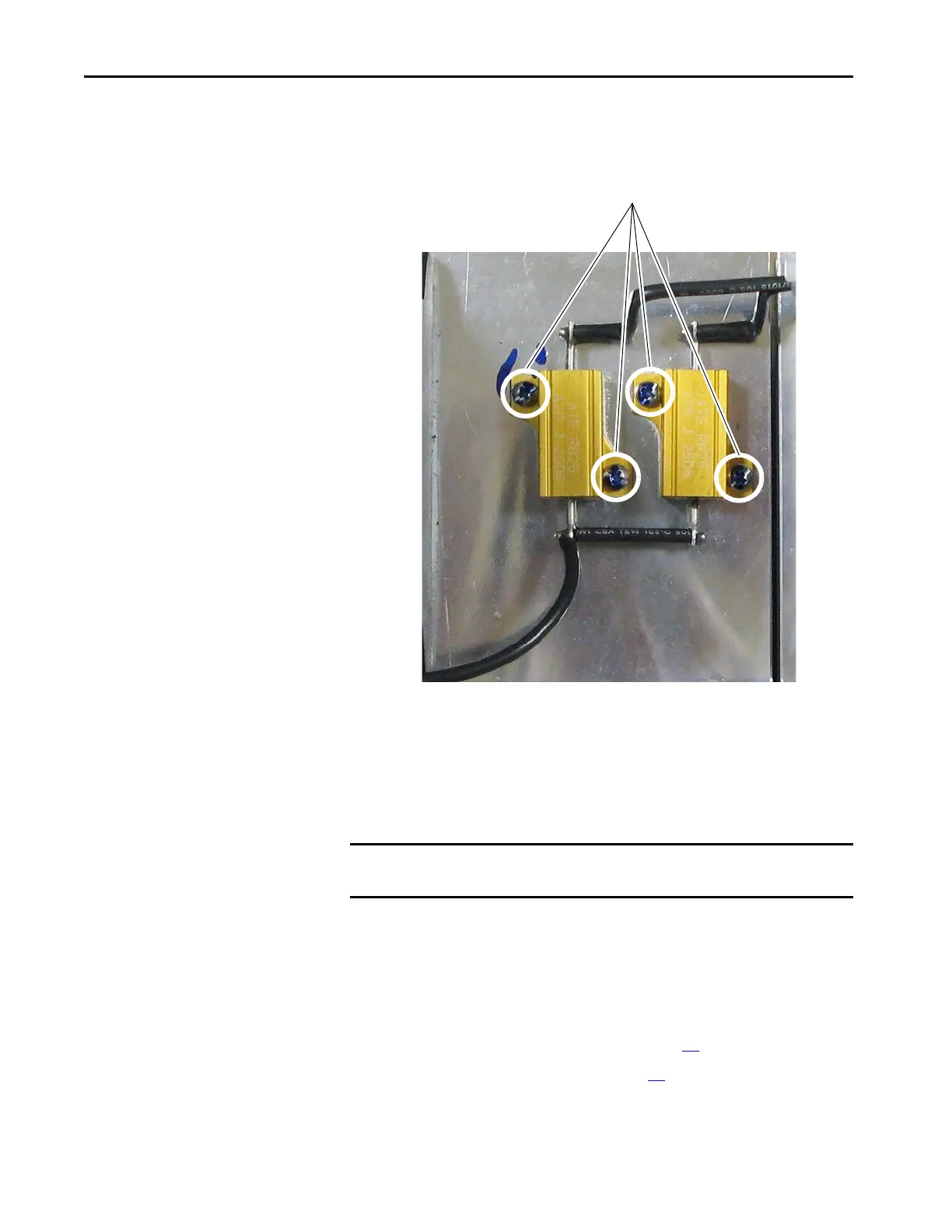
9. Remove the two screws that secure each resistor (six total) to the drive
heatsink and remove the resistors and AC line snubber board from the
drive.
Install the AC Line Snubber Circuit Board and Resistors
Install the AC line snubber board and resistors in reverse order of removal.
SCR Modules Replacement
Remove the SCR Modules
Follow these steps to remove SCR modules.
1. Read the General Safety Precautions on page 10
.
2. Remove power from the drive (see page 42
).
3. Remove the screws and washers that secure the plastic shields to the
bottom of the drive and remove the shields.
IMPORTANT Thermal grease must be applied to the bottom of the resistors before
securing them to the heatsink.

 Loading...


