Rockwell Automation Publication 20P-TG002B-EN-P - February 2018 79
Part Replacement Procedures Chapter 3
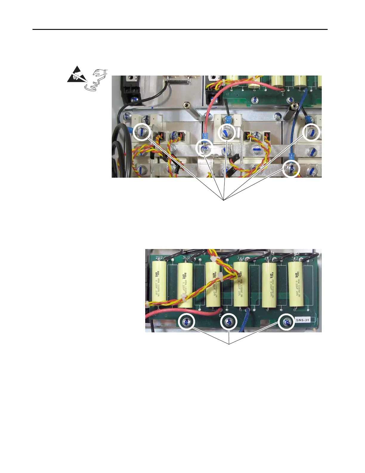
7. Remove the three screws and washers that secure the (black) wires from
the resistors to the bus bars and remove the wires.
8. Remove the three screws and washers that secure the AC line snubber
board to the drive frame and lift the board. Note: The wires from the
resistors are connected to the board. Therefore, the board cannot be
removed until the resistors are removed.

 Loading...


