30 Rockwell Automation Publication 20P-TG002B-EN-P - February 2018
Chapter 2 Component Test Procedures
Table 5 - SCR Gate to Cathode Junction Measurements for Non-Regenerative Drives
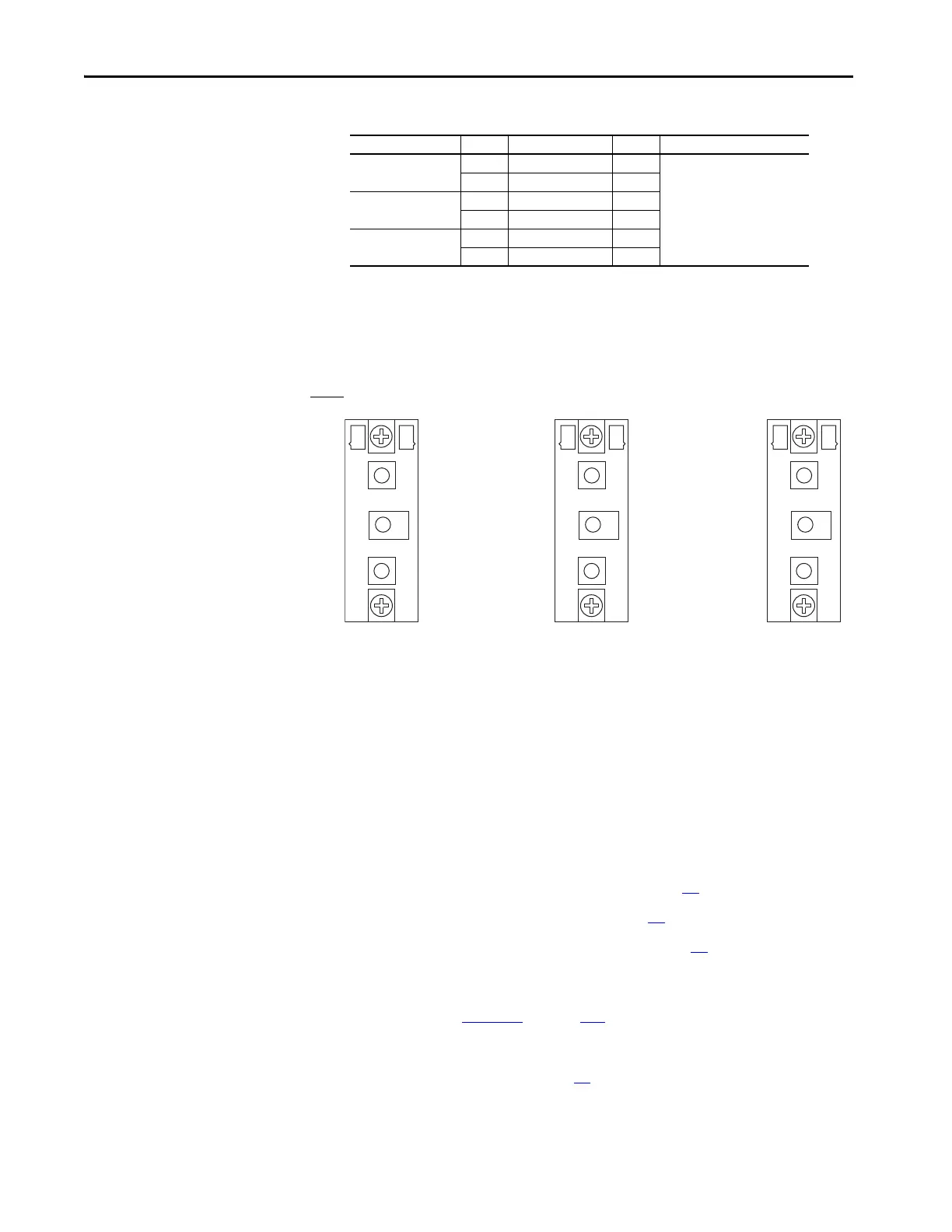
Figure 9 - SCR Gate Lead Connection Pinouts for Non-Regenerative Drives
Check the Pulse Transformer Board
The armature pulse transformer circuit board contains an isolated gate firing
circuit and also provides dv/dt protection for the armature SCR modules. A
malfunction of these devices will be indicated by either an Overcurrent fault
(F13), blown or tripped incoming protection devices or erratic motor
operation. Use the following procedure if a malfunction in this circuitry is
suspected.
1. Read the General Safety Precautions on page 10
.
2. Remove power from the drive (see page 42
).
3. Remove the pulse transformer board (see page 62
).
4. With a digital multimeter set for a “continuity check”, measure each
connection point on the pulse transformer board listed in the tables
below. See Figure 25
on page 114 for connector locations.
If any of the actual measurements are out of tolerance, replace the pulse
transformer board (see page 62
).
On SCR Module SCR Measure from To Nominal Meter Reading
01 01 Pin 6 Pin 7 5…20 Ω
(1)
(1) The actual reading varies depending upon the SCR manufacturer. Verify that the actual measured value is consistent
for all SCRs.
04 Pin 5 Pin 4
02 02 Pin 6 Pin 7
05 Pin 5 Pin 4
03 03 Pin 6 Pin 7
06 Pin 5 Pin 4
SCR Module 01 SCR Module 02 SCR Module 03
Gate Lead
Pinouts
4 56 7 4 56 7 4 56 7

 Loading...


