Rockwell Automation Publication 20P-TG002B-EN-P - February 2018 29
Component Test Procedures Chapter 2
If a measurement is outside of the range specified in the table, or if one reading
deviates significantly from the majority, then module replacement may be
necessary (see page 80
).
Table 4 - SCR Gate to Cathode Junction measurements for Regenerative Drives
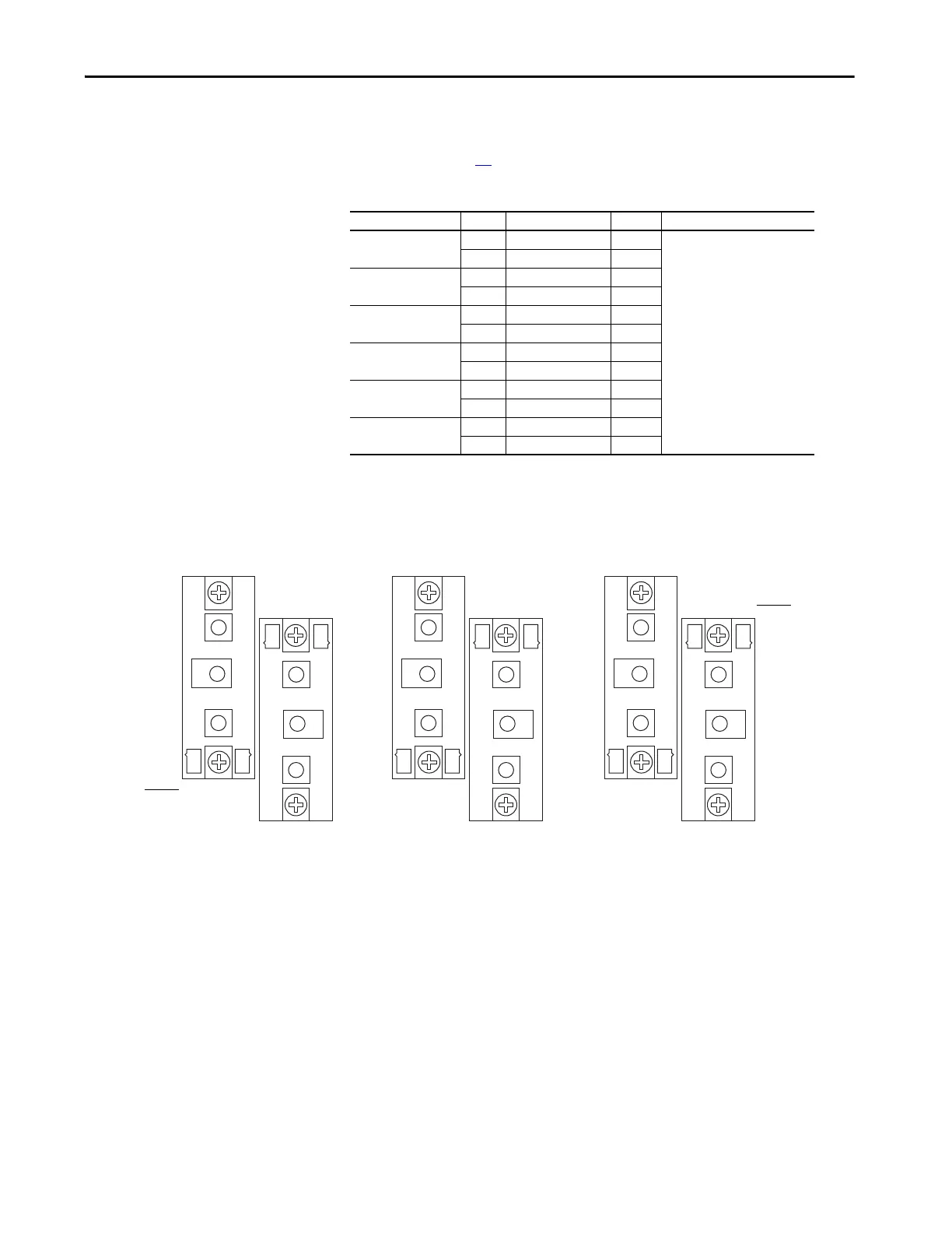
Figure 8 - SCR Gate Lead Connection Pinouts for Regenerative Drives
On SCR Module SCR Measure from To Nominal Meter Reading
1 1 Pin 5 Pin 4 5…20 Ω
(1)
(1) The actual reading varies depending upon the SCR manufacturer. Verify that the actual measured value is consistent
for all SCRs.
4 Pin 6 Pin 7
22Pin 5Pin 4
5 Pin 6 Pin 7
33Pin 5Pin 4
6 Pin 6 Pin 7
01 01 Pin 6 Pin 7
04 Pin 5 Pin 4
02 02 Pin 6 Pin 7
05 Pin 5 Pin 4
03 03 Pin 6 Pin 7
06 Pin 5 Pin 4
1
2
3
2
1
3
1
2
3
2
1
3
1
2
3
2
1
3
SCR Module 1
SCR Module 01
SCR Module 2
SCR Module 02
SCR Module 3
SCR Module 03
5 4
7 6
4 5
6 7
Gate Lead
Pinouts
Gate Lead
Pinouts
5 4
7 6
5 4
7 6
4 5
6 7
4 5
6 7

 Loading...


