28 Rockwell Automation Publication 20P-TG002B-EN-P - February 2018
Chapter 2 Component Test Procedures
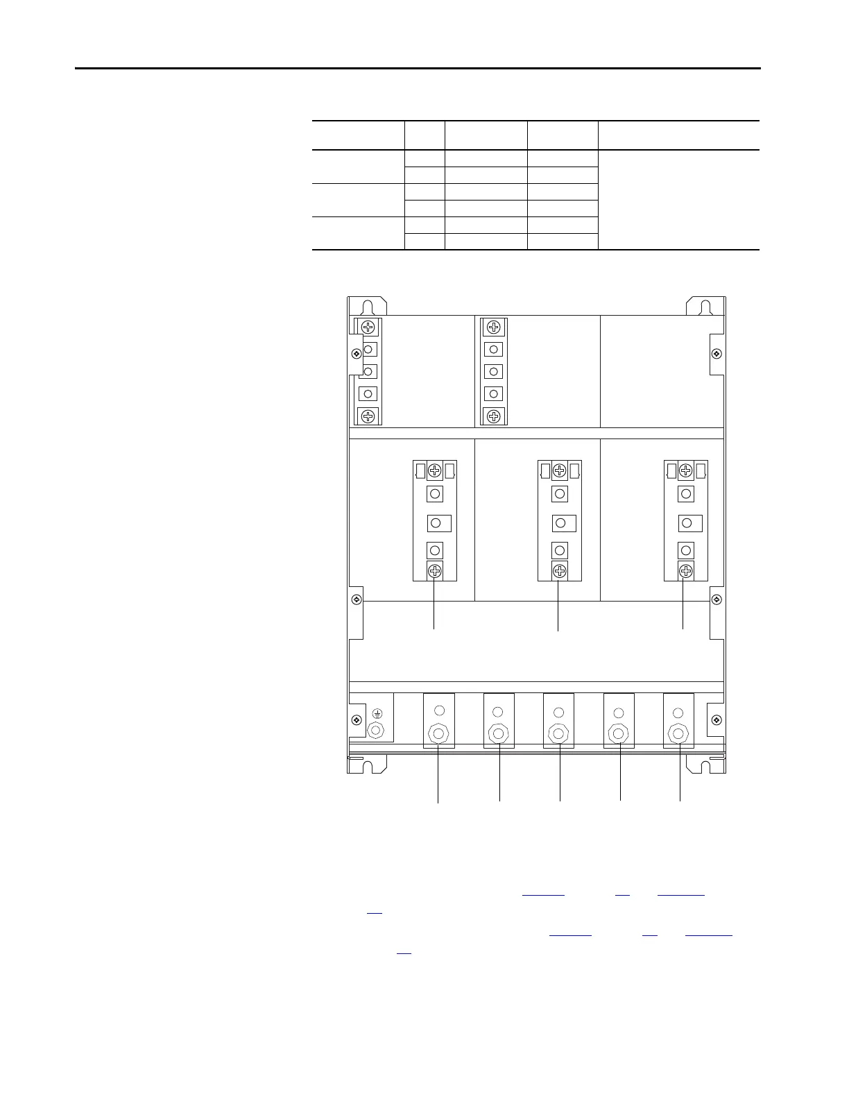
Table 3 - SCR Anode to Cathode Junction Measurements for Non-Regenerative Drives
Figure 7 - Non-Regenerative Drive SCR Module Layout
5. Check the gate to cathode junction of each SCR. With a digital
multimeter set to Ohms, measure the resistance of each SCR junction.
• For regenerative drives, see Tabl e 4
on page 29 and Figure 8 on page
29
.
• For non-regenerative drives, see Tabl e 5
on page 30 and Figure 9 on
page 30
.
On SCR Module SCR Measure from
Terminal
To Terminal Nominal Meter Reading
01 01 U C “open circuit” or “MΩ” range
04 U D
02 02 V C
05 V D
03 03 W C
06 W D
U
V
C
D
W
2
1
3
2
1
3
2
1
3
SCR Module 01 SCR Module 02 SCR Module 03
U CVDW

 Loading...


