Rockwell Automation Publication 20P-TG002B-EN-P - February 2018 119
Circuit Board Layouts and Connections Appendix B
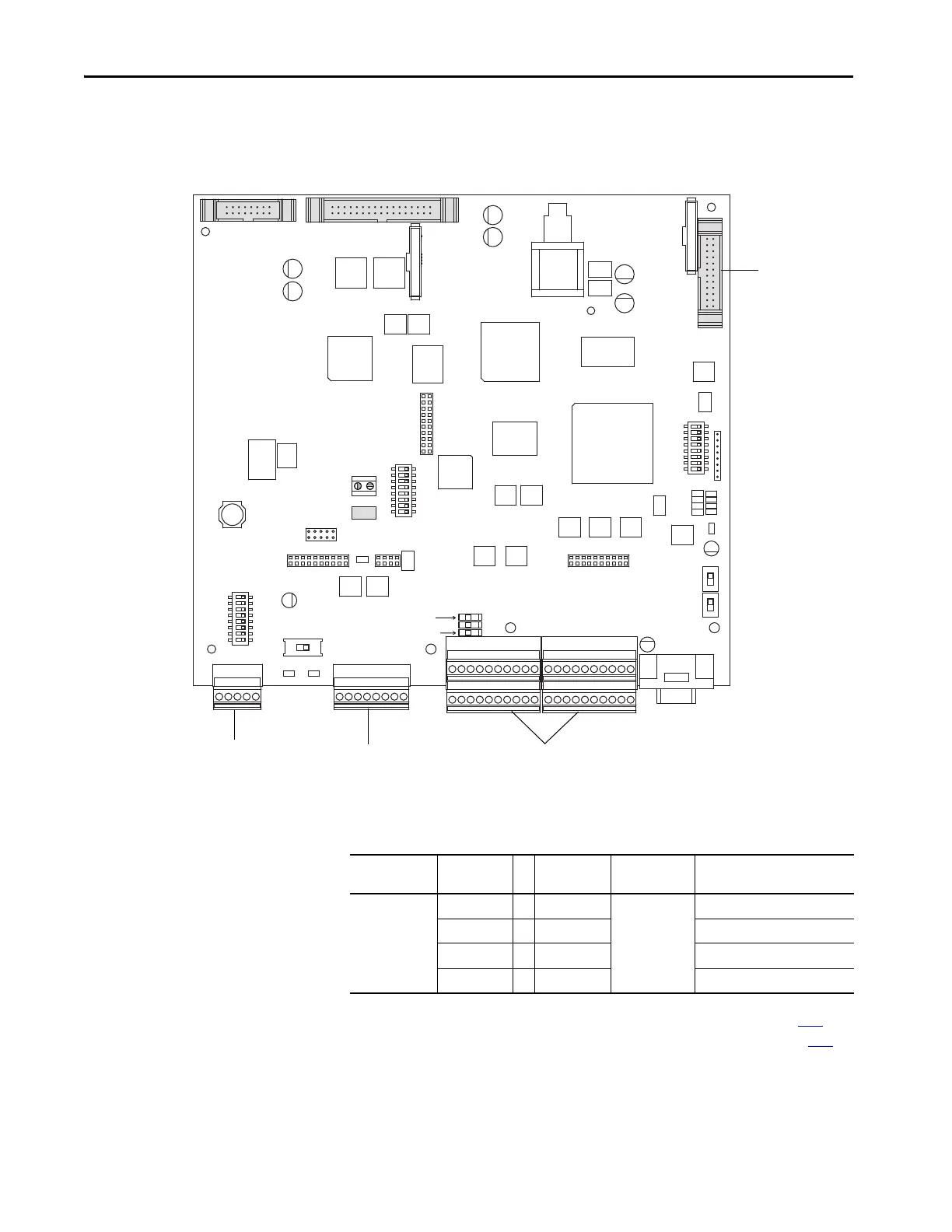
Control Board
Figure 27 - Control Board Layout
Table 27 - Control Board to Field Board Connections
See Pulse Transformer Board to Control Board Connections on page 116 and
Switching Power Supply Board to Control Board Connections on page 118
.
- A B C +
A+ A- B+ B- Z+ Z- COM +V
A+ A- B+ B- Z+ Z- COM +V
- A B C +
21 22 23 24 25 26 27 28 29 30
1 2 3 4 5 6 7 8 9 10
31 32 33 34 35 36 37 38 39 40
11 12 13 14 15 16 17 18 19 20
21 22 23 24 25 26 27 28 29 30
1 2 3 4 5 6 7 8 9 10
11 12 13 14 15 16 17 18 19 20
31 32 33 34 35 36 37 38 39 40
DEBUG
S15
S3
S2
S1
S0
RST
ACT
RUN
PWR
1 2 3 4 5 6 7 8
S18
S12
S10
S21
ENC_5 ENC_12
S4
1 2 3 4 5 6 7 8
S14
1 2 3 4 5 6 7 8
S20
S11
S9
ON
XR
XA
XFCD
To DPI board on
HIM Bezel
I/O terminal blocksEncoder terminal blockDC analog tachometer
terminal block
Control Board
Connector
Pin Number t
o
Pin Number Field Board
Connector
Description
XFCD1…1XFCD+15V
2…2 15V Common
3…3 -15V
4 … 4 Field CT burden resistors

 Loading...


