52 Rockwell Automation Publication 20P-TG002B-EN-P - February 2018
Chapter 3 Part Replacement Procedures
I/O Expansion Circuit Board
Replacement
Remove the I/O Expansion Circuit Board
Follow these steps to remove the I/O expansion circuit board.
1. Read the General Safety Precautions on page 10
.
2. Remove power from the drive (see page 42
).
3. Remove the protective covers from the drive (see page 43
).
4. If installed, remove the resolver feedback option board (see page 48
).
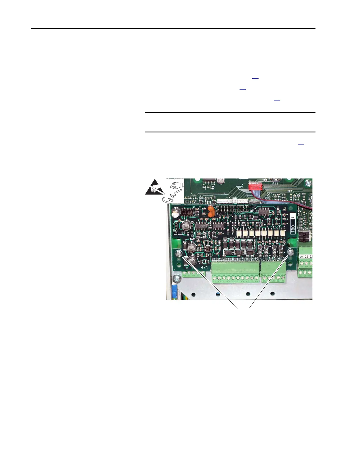
5. Remove the plug-in I/O terminal blocks with the wiring kept in place.
6. Remove the two M3 x 6 mm screws and washers that secure the I/O
expansion board to the stand-offs on the control board.
7. Carefully pull the I/O expansion board off connector XBB on the
control board.
IMPORTANT Mark all connections and wires before removal to avoid incorrect
wiring during reassembly.
6
Tightening torque:
1.0 N•m (8.9 lb•in)

 Loading...


