90 Rockwell Automation Publication 20P-TG002B-EN-P - February 2018
Chapter 3 Part Replacement Procedures
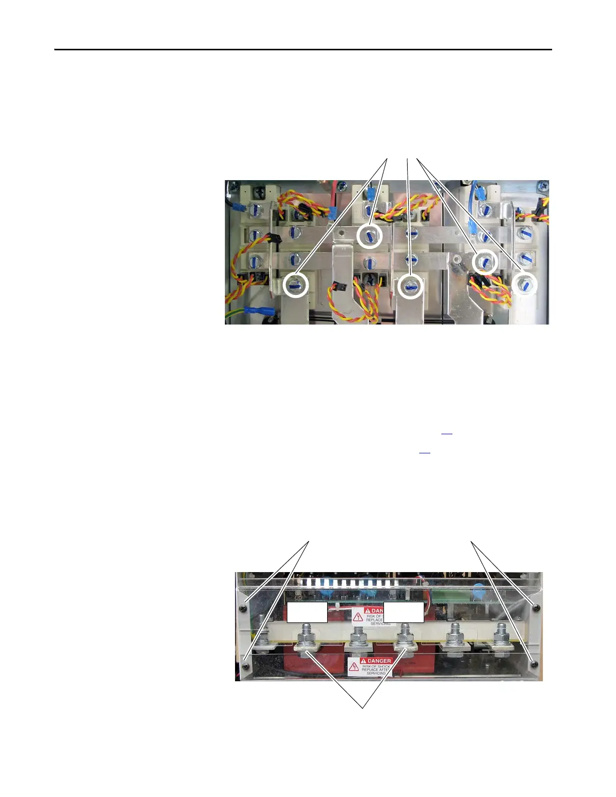
• For regenerative drives, five of the bolts are 24 mm long and the rest are
20 mm long. For non-regenerative drives, two of the bolts are 24 mm
long and the rest are 20 mm long. Install the 24 mm bolts in the
following locations:
AC Current Transducers
Replacement
Remove the AC Current Transducers
Follow these steps to remove the AC current transducers.
1. Read the General Safety Precautions on page 10
.
2. Remove power from the drive (see page 42
).
3. Remove the screws and washers that secure the plastic shields to the
bottom of the drive and remove the shields.
4. Remove the bolts, washers and wiring from the U and V phase AC input
power terminals.
24 mm bolt locations
Regenerative Drive Shown
3
3
U Phase V Phase
4
Bottom View

 Loading...


