Rockwell Automation Publication 20P-TG002B-EN-P - February 2018 89
Part Replacement Procedures Chapter 3
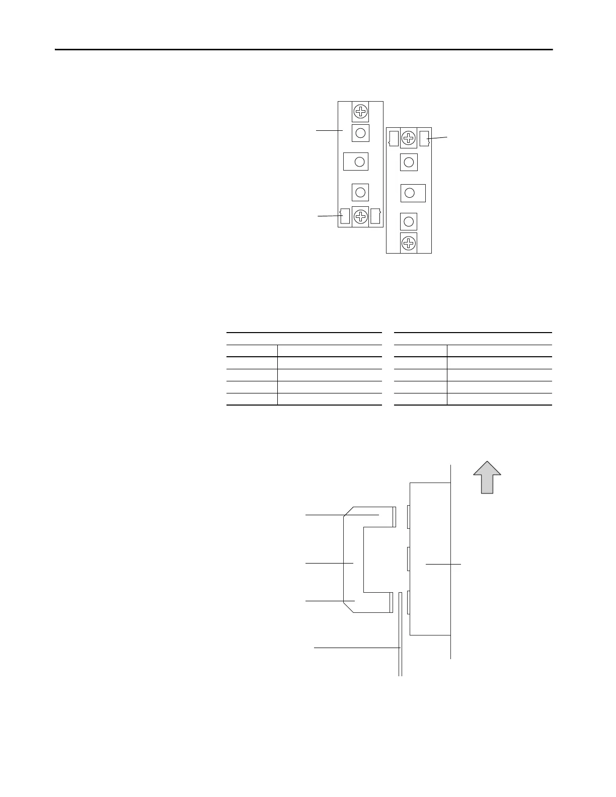
• Use the following orientation for installing the SCR modules:
• Use the following table to determine the proper tightening torque for
the bus bars connected to the SCR modules:
• For regenerative drives, the longer leg of the intermediate AC input bus
bars connect to the top of the SCR modules:
230V AC Input 460V AC Input
Part Number Final Torque Part Number Final Torque
SK-20P-S7F48 4.5…5.5 N
•m (40…48.7 lb•in) SK-20P-S7F78 4.5…5.5 N•m (40…48.7 lb•in)
SK-20P-S7F49 4.5…5.5 N
•m (40…48.7 lb•in) SK-20P-S7F79 4.5…5.5 N•m (40…48.7 lb•in)
SK-20P-S7F42 11…13 N
•m (97.4…115 lb•in) SK-20P-S7F41 11…13 N•m (97.4…115 lb•in
SK-20P-S727F 11…13 N
•m (97.4…115 lb•in) SK-20P-S737F 11…13 N•m (97.4…115 lb•in)
Gate leads at top
Gate leads at bottom
This SCR module only
present in regenerative
drives.
Intermediate
bus bar
Phase U, V, or W
bus bar
SCR module on
heatsink
Top of Drive
Long leg
Short leg

 Loading...


