36 Rockwell Automation Publication 20P-TG002B-EN-P - February 2018
Chapter 2 Component Test Procedures
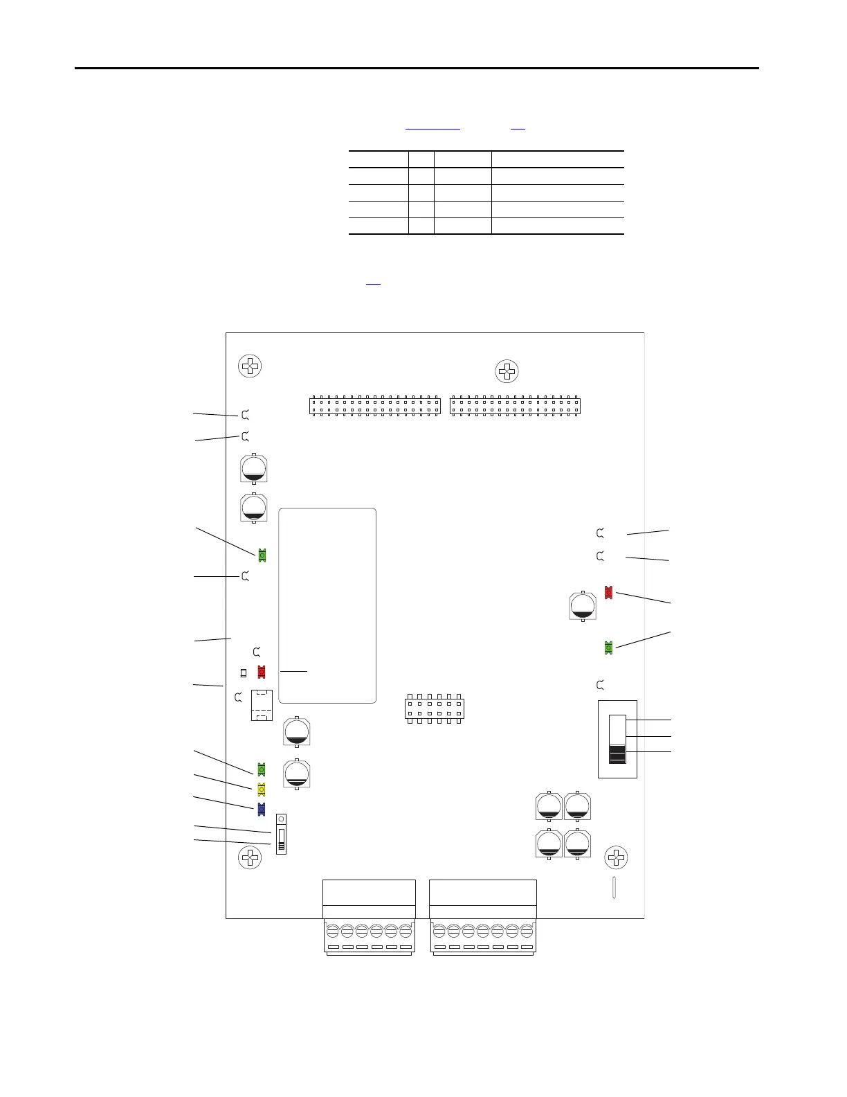
• Measure the signal voltage at the testpoints as indicated in the following
table. See Figure 12
on page 36 for testpoint locations.
If any of the voltage measurements fails, replace the resolver interface board
(see page 48
).
Figure 12 - Resolver Interface Board Testpoint Locations
Testpoint to Testpoint Measurement
+12V … 0V12 12V DC ±5%
-12V … 0V12 -12V DC ±5%
+24V_VI … 0V24 24V DC ±5%
+5V … 0V5 5V DC ±5%
P3P2
TB1 TB2
+12V
-12V
0V12
+24V_VI
0V24
S2
S1
+VR
0V5
+5V
D10
D3
D18D16D12
D26
D11
F1
+12V
-12V
0V12
+24V_VI
0V24
+5V
0V5
D26
D11
D10
D18
D16
D12
D3
S1 +5V pos.
S1 +12V pos.
S1 +24V pos.
S2 Internal supply pos.
S2 External supply pos.

 Loading...


