64 Rockwell Automation Publication 20P-TG002B-EN-P - February 2018
Chapter 3 Part Replacement Procedures
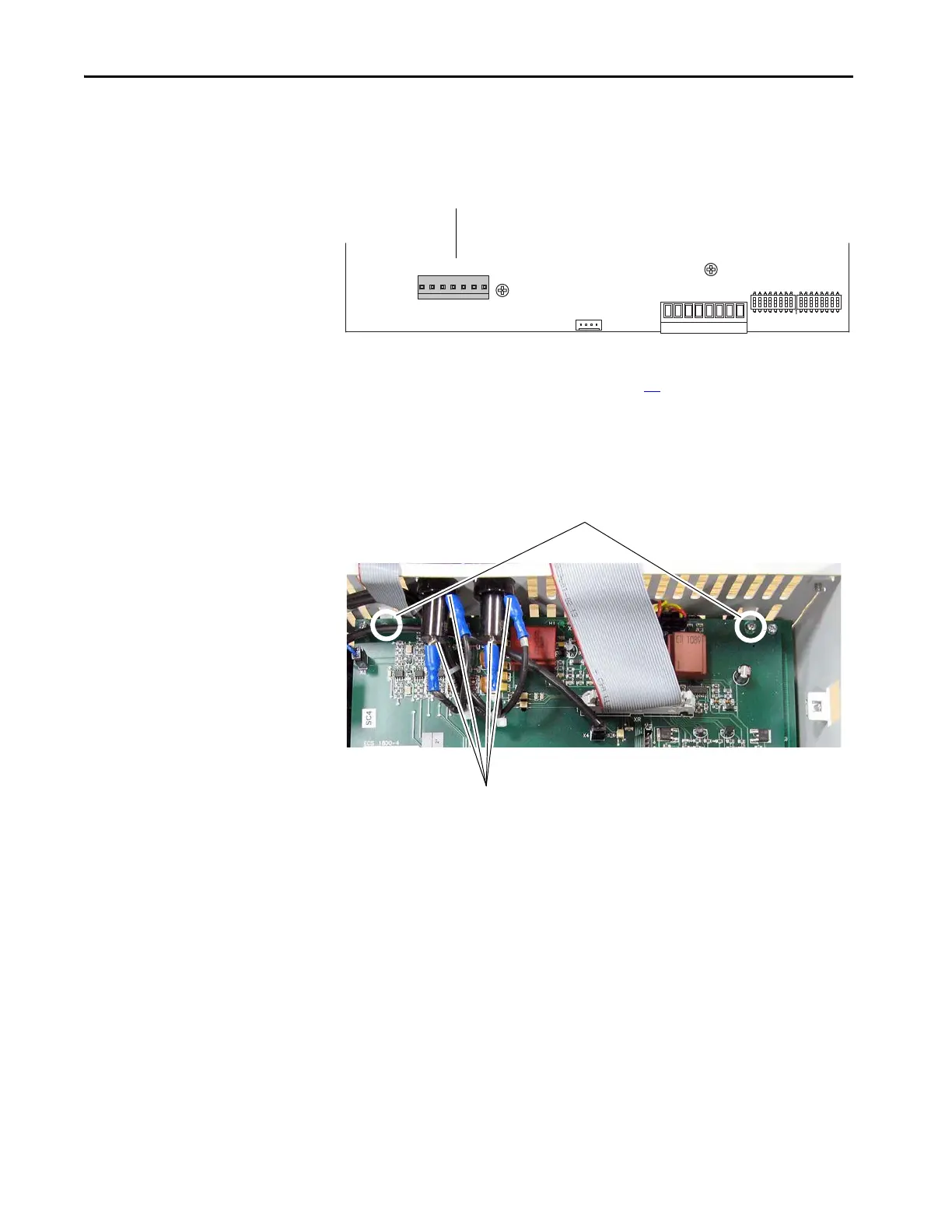
8. For Pulse Transformer boards with an armature voltage feedback
terminal block, FIR2-XX, rev. “N” and higher, remove the connector
from XCD_IO on the lower left corner of the board.
9. Move the control EMI shield (see page 58
).
10. Remove the two screws that secure the air flow plate to the top of the
pulse transformer board and lift the plate off the drive chassis. Note that
the air flow plate cannot be completely removed due to the fuse
connections at FU1 and FV1.
XCD_IO
C
XTA
XM
D
78 79 35 36 75 76 U2 V2
S3 S4
1

 Loading...


