Rockwell Automation Publication 20P-TG002B-EN-P - February 2018 17
Component Test Procedures Chapter 2
3. Remove the cables from connector XR and XFCD on the control board
and use an ohmmeter to check between all voltage test points and
common on the control board for possible short circuit conditions. The
ohmmeter measurements should be greater than 200 kΩ. If any low
resistance measurements are found, replace the control board.
4. Using an ohmmeter, measure between pins 1 and 2 and pins 3 and 2 on
the XFCD cable connector. The resistance measurement for both tests
should be greater than 200 kΩ. If a lower resistance value is measured,
replace field board.
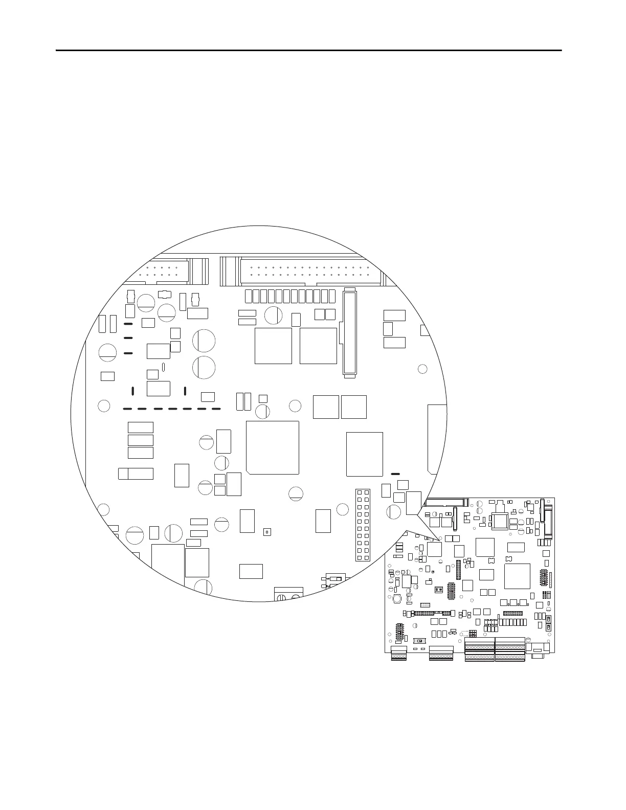
Figure 1 - Control Board Testpoints - Upper Left
- A B C +
A+ A- B+ B- Z+ Z- COM +V
A+ A- B+ B- Z+ Z- COM +V
- A B C +
21 22 23 24 25 26 27 28 29 30
1 2 3 4 5 6 7 8 9 10
31 32 33 34 35 36 37 38 39 40
11 12 13 14 15 16 17 18 19 20
21 22 23 24 25 26 27 28 29 30
1 2 3 4 5 6 7 8 9 10
11 12 13 14 15 16 17 18 19 20
31 32 33 34 35 36 37 38 39 40
DEBUG
S15
S3
S2
S1
S0
RST
ACT
RUN
PWR
1 2 3 4 5 6 7 8
S18
S12
S10
S21
ENC_5
S4
1 2 3 4 5 6 7 8
S14
1 2 3 4 5 6 7 8
S20
S11
S9
ON
ON
XY18
XY17
XY19
XY9
XY8
XY12
XY10
XY11 XY6 XY5
XY21
XY22
XY20
ENC_12

 Loading...


