Rockwell Automation Publication 20P-TG002B-EN-P - February 2018 23
Component Test Procedures Chapter 2
4. Verify that the value of parameter 280 [Nom Mtr Fld Amps] matches
the rated field current value on motor nameplate and make any
necessary corrections.
5. Remove the protective covers (see page 43
).
6. Measure the field current signal on the green LA-LB terminal located on
the control board: LA is the ground and LB is field current signal. The
measured value of the field current at LA-LB should be equal to the
value of parameter 374 [Drv Fld Brdg Cur]. If these values are
equivalent, the voltage across these terminals should be 1.66 VDC.
Note: For lower field current values, the voltage will be proportional.
For example, if the field is set up for 2 A and the motor is rated for 1.5 A,
the measurement at LA-LB will be 1.245 VDC (1.5 / x = 2 / 1.66).
• If the voltage measurement is incorrect, continue with step 7 below.
• If the voltage measurement is correct, but the “Field Current Loss”
fault still exists, replace the control board (see page 55
).
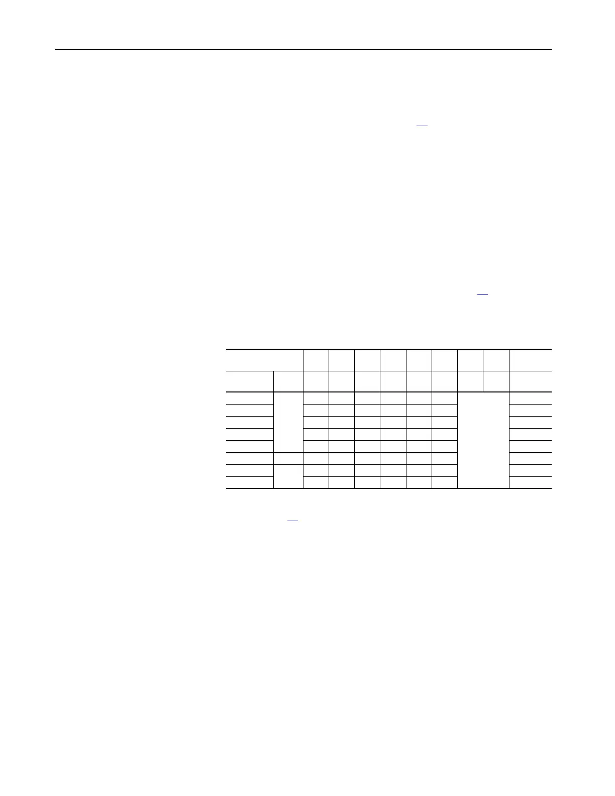
7. Using an ohmmeter, measure the resistance across terminals LA-LB to
verify that the value equals the equivalent resistance as indicated in the
table below (set with DIP switch S14 on the control board).
• If the resistance measurement is incorrect, replace the field board (see
page 75
).
Switch Ohms: 168.5 333.3 182 36.4 845 1668 3333 – Equivalent
Resistance
Field Current
Scale
Field
Supply
S14-1 S14-2 S14-3 S14-4 S14-5 S14-6 S14-7 S14-8 Ohm
1 A 10 A OFF OFF OFF OFF OFF ON Not used
(OFF)
1668
2 A OFF OFF OFF OFF ON OFF 845
3 A OFF OFF OFF OFF ON ON 560.9
5 A OFF ON OFF OFF OFF OFF 333.3
10 A ON OFF OFF OFF OFF OFF 168.5
13 A 14 A ON OFF OFF OFF ON ON 129.6
17 A 20 A OFF ON ON OFF ON ON 97.3
20 A ON OFF ON OFF OFF ON 83.1

 Loading...


