Rockwell Automation Publication 20P-TG002B-EN-P - February 2018 25
Component Test Procedures Chapter 2
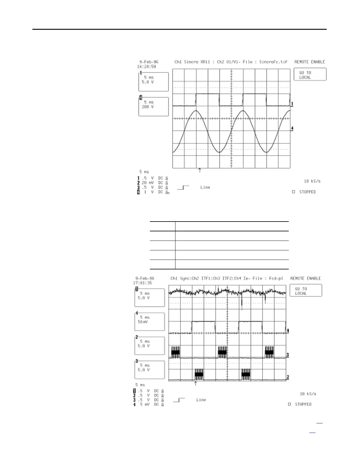
This signal is a square wave signal with a 90° lag phase displacement
compared to the AC voltage signal.
2. Measure the gate signals at pins XR-1 and XR-2 on the cable. The figure
below displays the following signals from top to bottom:
• If the gate signals are missing, replace the control board (see page 55
).
• If the gate signals are present, replace the field board (see page 75
).
Channel Signal
1U1-V1 Sync
4 Ie - LEM current feedback signal taken on LA-LB terminal
2ITF1 pulse
3ITF2 pulse
LA-LB
U1-V1 Sync
ITF1 Pulse
ITF2 Pulse

 Loading...


