EasyManuals Logo

Rockwell Automation Allen-Bradley PowerFlex 20P Hardware Service Manual

Rockwell Automation Allen-Bradley PowerFlex 20P
130 pages
To Next Page IconTo Next Page
To Previous Page IconTo Previous Page
Page #44 background imageLoading...
Page #44 background image
44 Rockwell Automation Publication 20P-TG002B-EN-P - February 2018
Chapter 3 Part Replacement Procedures
3. Disconnect the DPI cable from the HIM assembly.
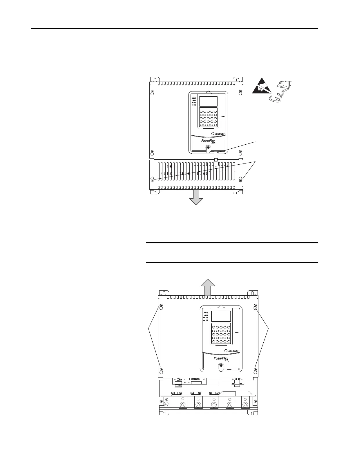
4. Loosen, but do not remove, the screws that secure the bottom cover to
the drive, then slide the cover down and off the drive chassis.
5. Loosen, but do not remove, the screws that secure the top cover to the
drive, then slide the cover up and off the drive chassis.
IMPORTANT The HIM assembly is connected via a cable to the Control board and
therefore will not pull free from the drive until disconnected.
3
=
Tightening torque:
1.5 N
m (13.3 lbin)
4
U
V
C
D
W
Tightening torque:
1.5 N
m (13.3 lbin)
5
Tightening torque:
1.5 N
m (13.3 lbin)
5

Table of Contents

Other manuals for Rockwell Automation Allen-Bradley PowerFlex 20P

Questions and Answers:

Question and Answer IconNeed help?

Do you have a question about the Rockwell Automation Allen-Bradley PowerFlex 20P and is the answer not in the manual?

Rockwell Automation Allen-Bradley PowerFlex 20P Specifications

General IconGeneral
BrandRockwell Automation
ModelAllen-Bradley PowerFlex 20P
CategoryDC Drives
LanguageEnglish

Related product manuals