Rockwell Automation Publication 20P-TG002B-EN-P - February 2018 67
Part Replacement Procedures Chapter 3
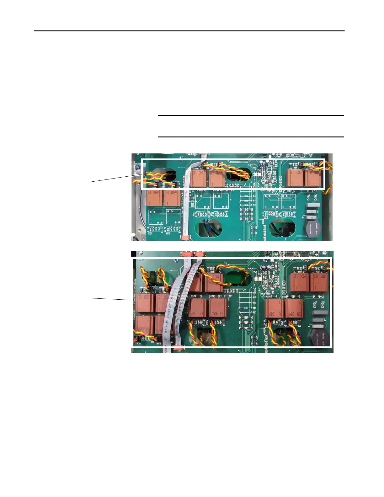
14. Remove the appropriate gate leads:
• For non-regenerative drives, remove each pair of (orange and yellow)
gate lead cables from connectors KG01…KG06 and push each lead
through the appropriate opening in the board.
• For regenerative drive, remove each pair of (orange and yellow) gate
lead cables from connectors KG01…KG06 and KG1…KG6 and push
each lead through the appropriate opening in the board.
15. Remove the seven screws that secure the board to the stand-offs on the
drive chassis and remove the boards from the drive.
IMPORTANT Carefully remove the gate leads by grasping the connector. DO NOT
pull the gate leads off by pulling on the wires.
14 ( regenerative drives)
14 (non-regenerative drives)

 Loading...


