4-54 Bulletin 284G Programmable Parameters for Sensorless Vector Controllers
Parameters 240…247 are only active if 138 (Speed Reference) is set
to 6 Stp Logic.
These parameters can be used to create a custom profile of frequency
commands. Each step can be based on time, status of a Logic input, or
a combination of time and the status of a Logic input.
Digits 0…3 for each (Stp Logic x) parameter must be programmed
according to the desired profile.
A Logic input is established by setting a digital input, Parameters
151…154 (Digital Inx Sel), to 23 Logic In1 and/or 24 Logic In2.
A time interval between steps can be programmed using Parameters
250…257 (Stp Logic Time x). See Table 4.8 for related parameters.
The speed for any step is programmed using Parameters 170…177
(Preset Freq x).
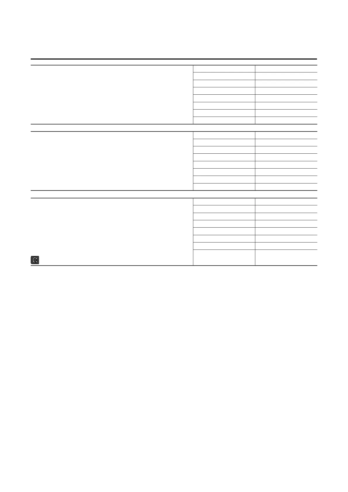
PID Deadband
Sets the lower limit of the PID output.
Parameter Number 238
Access Rule GET/SET
Data Type UINT
Group Advanced Program Group
Units 0.1%
Minimum Value 0.0%
Maximum Value 10.0%
Default Value 0.0%
PID Preload
Sets the value used to preload the integral component on start or enable.
Parameter Number 239
Access Rule GET/SET
Data Type UINT
Group Advanced Program Group
Units 0.0 Hz
Minimum Value 0.0 Hz
Maximum Value 400.0 Hz
Default Value 0.0 Hz
A240 (Stp Logic 0)
A241 (Stp Logic 1)
A242 (Stp Logic 2)
A243 (Stp Logic 3)
A244 (Stp Logic 4)
A245 (Stp Logic 5)
A246 (Stp Logic 6)
A247 (Stp Logic 7)
Parameter Number 240…247
Access Rule GET/SET
Data Type UINT
Group Advanced Program Group
Units —
Minimum Value 0001
Maximum Value baFF
Default Value 00F1
Stop drive before changing this parameter.

 Loading...


