Group Motor Installations D-3
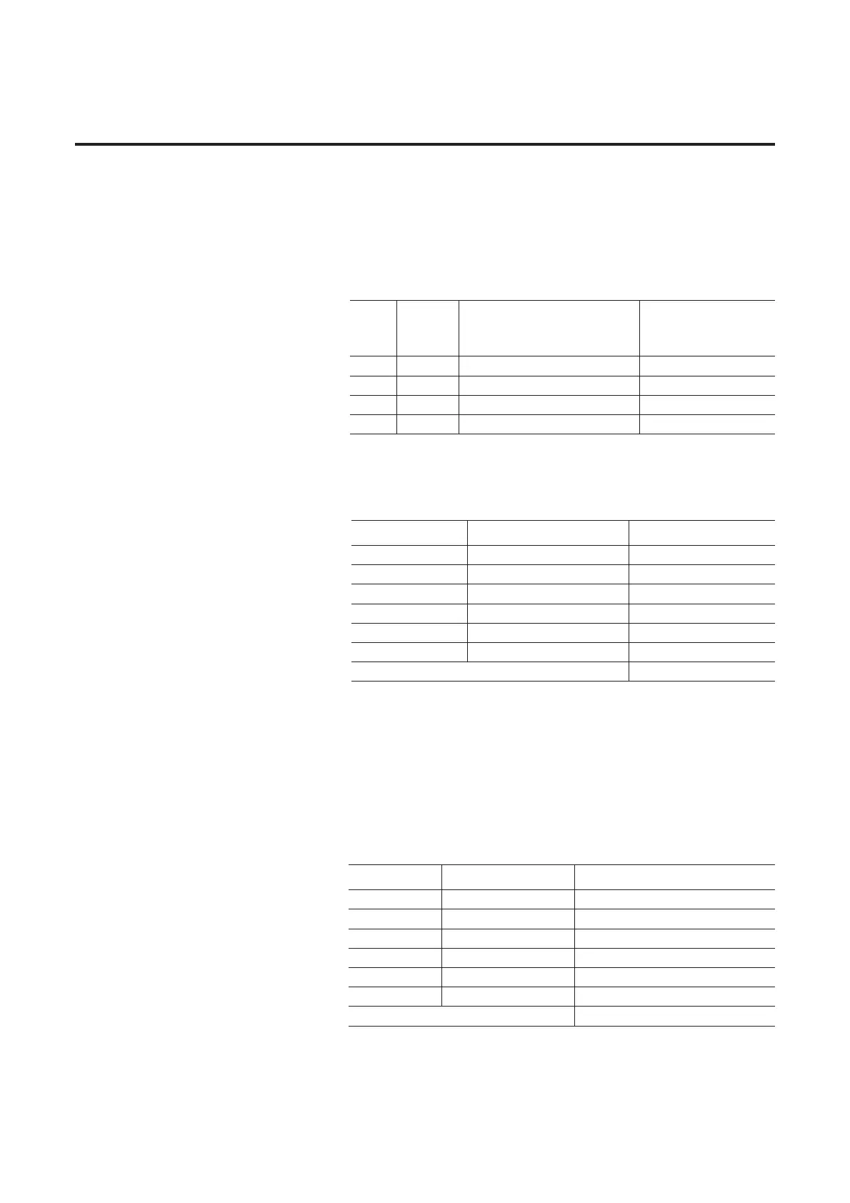
To design the motor circuit using a time delay fuse from NEC Table
430.52 to the rules of NEC 430.53C we start with the largest motor,
10 Hp, and calculate 14 A x 175% = 24.5 A. To this we add the FLC
of the 5 Hp motor, 7.6 A, plus the other calculated drive currents for
the motors controlled by the VFD-ArmorStarts. The calculated drive
currents are given in the following Table:
The total current for the fuse ampacity is calculated in the following
Table:
Therefore the standard fuse available not exceeding 46.4 A is a 40 A
fuse.
To calculate the wire ampacity and therefore the size of the motor
branch conductor we use NEC 430.24 and calculate the sum of 125%
of the largest motor’s FLC plus the FLC of the other motors in the
group. The conductor ampacity calculation is given in the following
Table:
Motor
Hp
Motor FLC
(A)
Drive Input to Output Current Ratio
(See ArmorStart Users Manual -
Appendix A)
Calculated Drive Current
(A)
2 3.4 5.57 A/4.0 A = 1.39 3.4 x 1.39 = 4.72 A
1 2.1 3.45 A/2.3 A = 1.5 2.1 x 1.5 = 3.15 A
1 2.1 3.45 A/2.3 A = 1.5 2.1 x 1.5 = 3.15 A
1 2.1 3.45 A/2.3 A = 1.5 2.1 x 1.5 = 3.15 A
Motor Hp Motor FLC (A) TD Fuse Current (A)
10 14 24.5 A
5 7.6 7.6 A
2 3.4 4.72 A
1 2.1 3.15 A
1 2.1 3.15 A
1 2.1 3.15 A
Total Fuse Current 46.4 A
Motor Hp Motor FLC (A) Wire Current (A)
10 14 14A x 1.25 =17.5A
5 7.6 7.6A
2 3.4 4.89 A
1 2.1 3.15 A
1 2.1 3.15 A
1 2.1 3.15 A
Total Fuse Current 39.4 A

 Loading...


