2-9
Installation
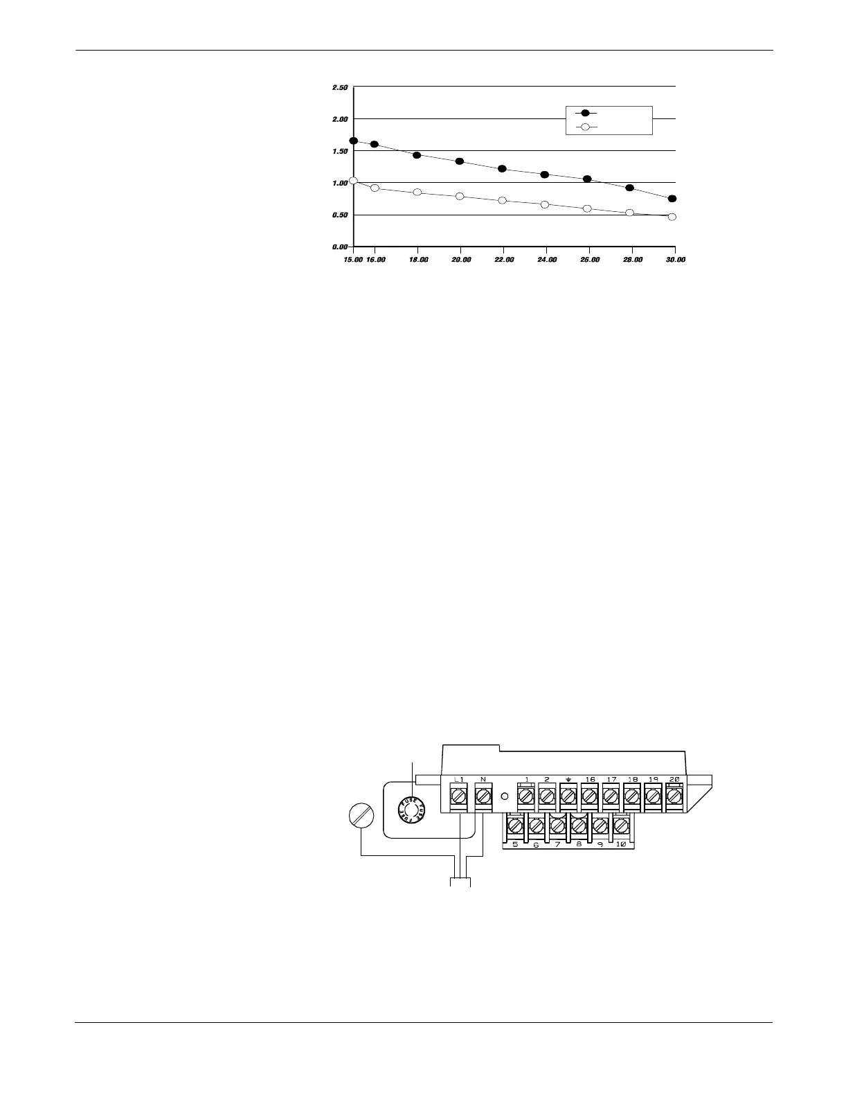
FIGURE 2-5. Supply Current versus Input Voltage
OPTIONS,
CONSIDERATIONS, AND
PROCEDURES
If your application of the Model 8712C/U/H includes the use of options
such as multidrop communications, positive zero return (PZR),
auxiliary output control, or pulse output, certain requirements may
apply in addition to those previously listed. Be prepared to meet these
requirements before attempting to install and operate the
Model 8712C/U/H.
Connect Transmitter Power
To connect power to the transmitter, complete the following steps.
1. Ensure that the power source and connecting cable meet the
requirements outlined in Transmitter Input Power on page 2-7.
2. Turn off the power source.
3. Open the power terminal cover.
4. Run the power cable through the conduit to the transmitter.
5. Loosen the terminal guard for terminals L1 and N.
6. Connect the power cable leads as follows:
• Connect ac Neutral/dc- to terminal N.
• Connect ac Line/dc+ to terminal L1.
• Connect ac Ground/dc Ground to the ground screw.
FIGURE 2-6. Transmitter
Power Connections
Surge
Nominal
upp
y
urrent
mperes
Input Voltage (Volts)
8712-0388A
Transmitter
Power Cable
ac Neutral or dc–
ac Line or dc+
ac Ground or
dc Ground
Fuse
8712-8712E01B