2-5
Installation
Changing Hardware
Switch Settings
In most cases, it is not necessary to change the setting of the hardware
switches. If you need to change the switch settings, complete the steps
outlined below:
NOTE
The hardware switches are located on the solder side of the electronics
board and changing their settings requires opening the electronics
housing. If possible, carry out these procedures away from the plant
environment in order to protect the electronics.
1. Disconnect power to the transmitter.
2. Loosen the housing door screw and open the housing door.
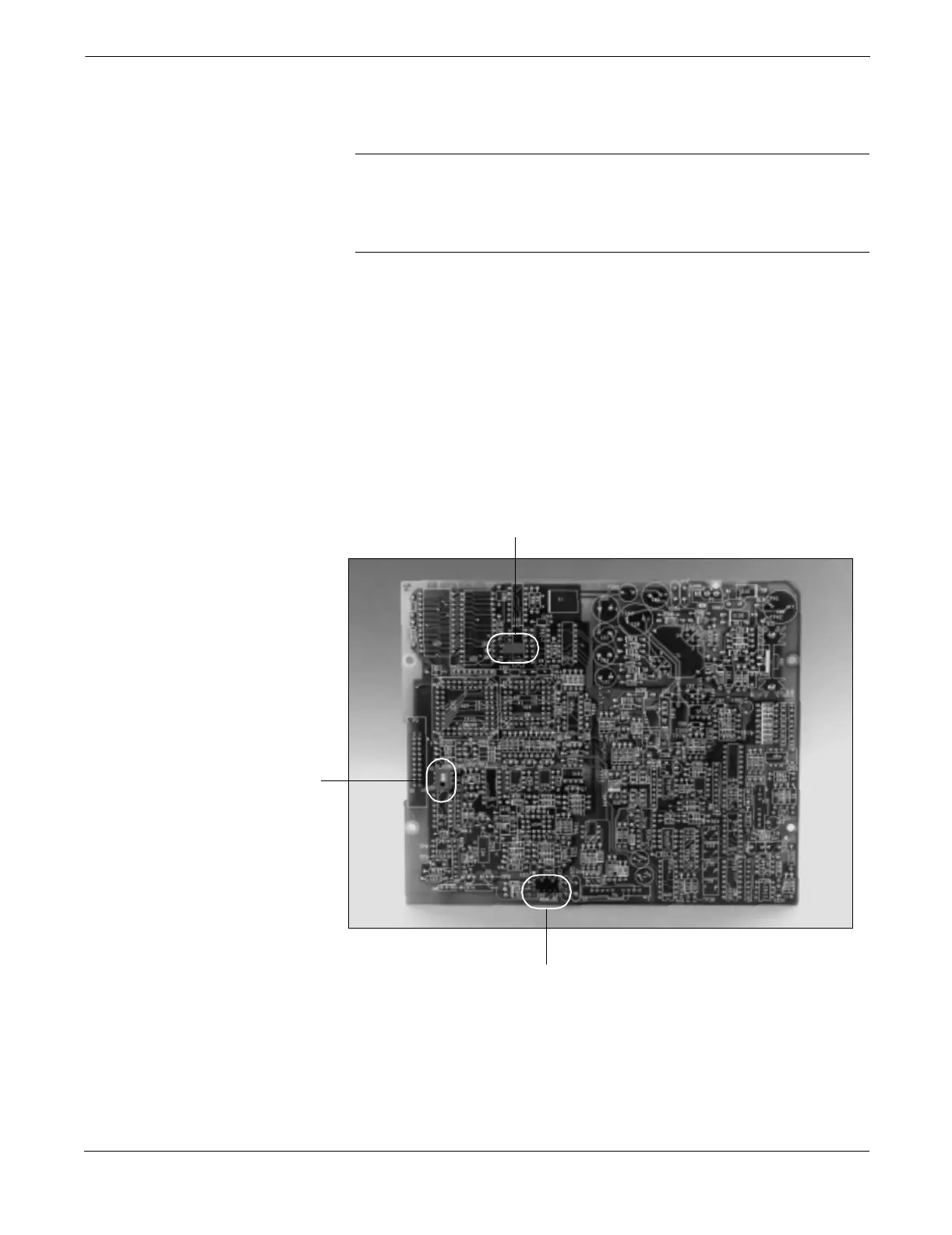
3. Identify the location of each switch or jumper (see Figure 2-2).
4. Switches: Change the setting of the desired switches with a
small screwdriver.
Jumpers: Pull the jumper off of its current setting and connect to
the desired setting.
5. Close the housing door and tighten the housing door screw.
FIGURE 2-2. Model 8712C/U/H Electronics Board and Hardware Switches/Jumpers
Electrical Considerations
Before making any electrical connections to the Model 8712C/U/H,
consider the following standards and be sure to have the proper power
supply, conduit, and other accessories.
Failure
Alarm Mode
Internal/External
Analog Power
Transmitter
Security
8712-013AB