B-13
Wiring Diagrams
Model 10D1430 Flowtube
(Integral) to Model 8712U
Transmitter
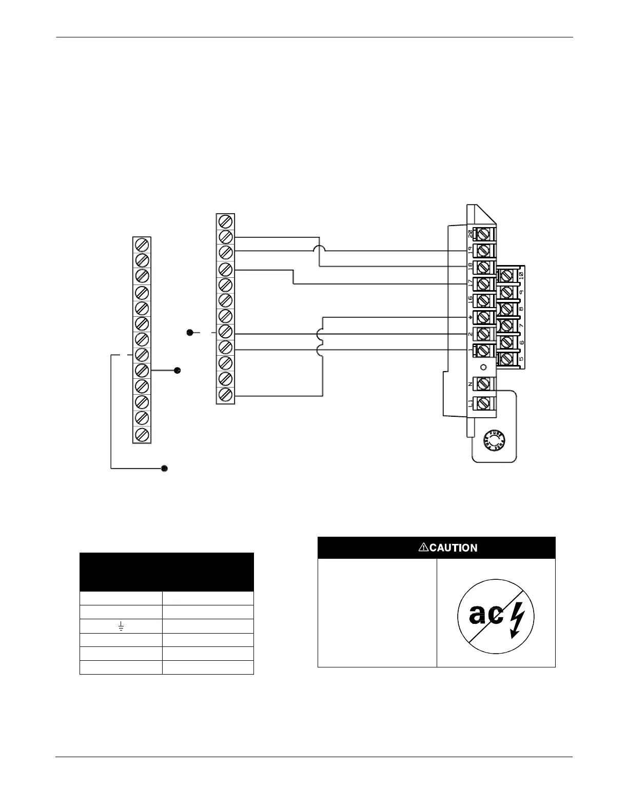
Connect coil drive and electrode cables as shown in Figure B-12.
FIGURE B-12. Wiring Diagram for
Fischer and Porter Flowtube Model
10D1430 (Integral) and Rosemount
Model 8712U
Electrode Connections
ROSEMOUNT MODEL
8712U TRANSMITTER
To L2
(Disconnect)
To Calibration Device
(Disconnect)
1
2
3
7
6
8
L2
L1
U2
U1
1
2
3
7
6
L2
L1
U2
U1
G
TB1
TB2
Coil Connections
8712-1000A01E
This is a pulsed dc
magnetic flowmeter. Do
not connect ac power
to the flowtube or to
terminals 1 and 2 of
the transmitter,or
replacement of the
electronics board will
be necessary.
TABLE B-12. Fischer and Porter
Model 10D1430 (Integral) Flowtube
Wiring Connections
Rosemount
Model 8712U
Fischer and Porter
Model 10D1430
(Integral) Flowtubes
1L1
2L2
G
17 3
18 1
19 2