Model 8712C/U/H Magnetic Flowmeter Transmitters
2-10
Connect 4–20 mA Loop
External Power Source
The 4–20 mA output loop provides the process variable output from the
transmitter. Its signal may be powered internally or externally. The
default position of the internal/external analog power jumper is in the
internal position. The user-selectable power supply jumper is located on
the electronics board.
Internal
The 4–20 mA analog power loop may be powered from the transmitter
itself. Resistance in the loop must be 1,000 ohms or less. If a HART
Communicator or control system will be used, it must be connected
across a minimum of 250 ohms resistance in the loop.
External
HART multidrop installations require a 10–30 V dc external analog
power source (see Multidrop Communications on page 4-18). If a
HART Communicator or control system is to be used, it must be
connected across a minimum of 250 ohms resistance in the loop.
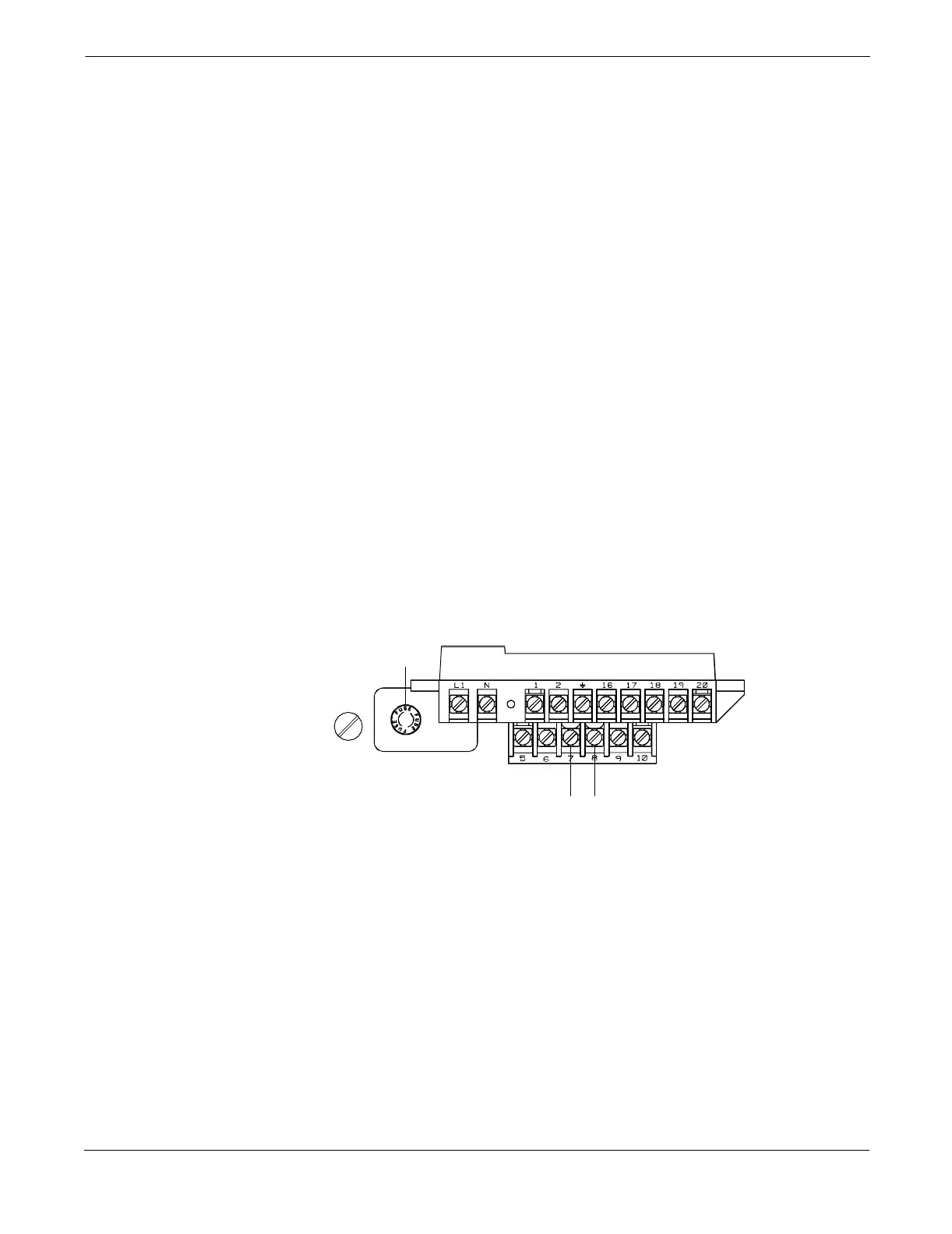
To connect external power to the 4–20 mA loop, complete the
following steps.
1. Ensure that the power source and connecting cable meet the
requirements outlined above and in Electrical Considerations
on page 2-5.
2. Turn off the transmitter and analog power sources.
3. Run the power cable into the transmitter.
4. Connect –dc to Terminal 8.
5. Connect +dc to Terminal 7.
FIGURE 2-7. 4–20 mA Loop Power Connections
–4–20 mA power+4–20 mA power
Fuse
8712-8712E01B