B-27
Wiring Diagrams
GENERIC
MANUFACTURER
FLOWTUBES
Generic Manufacturer
Flowtube to
Model 8712U Transmitter
Identify the Terminals
First check the flowtube manufacturer’s manual to identify the
appropriate terminals. Otherwise, perform the following procedure.
Identify coil and electrode terminals
1. Select a terminal and touch an ohmmeter probe to it.
2. Touch the second probe to each of the other terminals and record
the results for each terminal.
3. Repeat the process and record the results for every terminal.
Coil terminals will have a resistance of approximately 3-300 ohms.
Electrode terminals will have an open circuit.
Identify a chassis ground
1. Touch one probe of an ohmmeter to the flowtube chassis.
2. Touch the other probe to the each flowtube terminal and the
record the results for each terminal.
The chassis ground will have a resistance value of one ohm or less.
Wiring Connections
Connect the electrode terminals to Model 8712U terminals
18 and 19. The electrode shield should be connected to terminal 17.
Connect the coil terminals to Model 8712U terminals 1, 2, and
.
If the Model 8712U Transmitter indicates a reverse flow condition,
switch the coil wires connected to terminals 18 and 19.
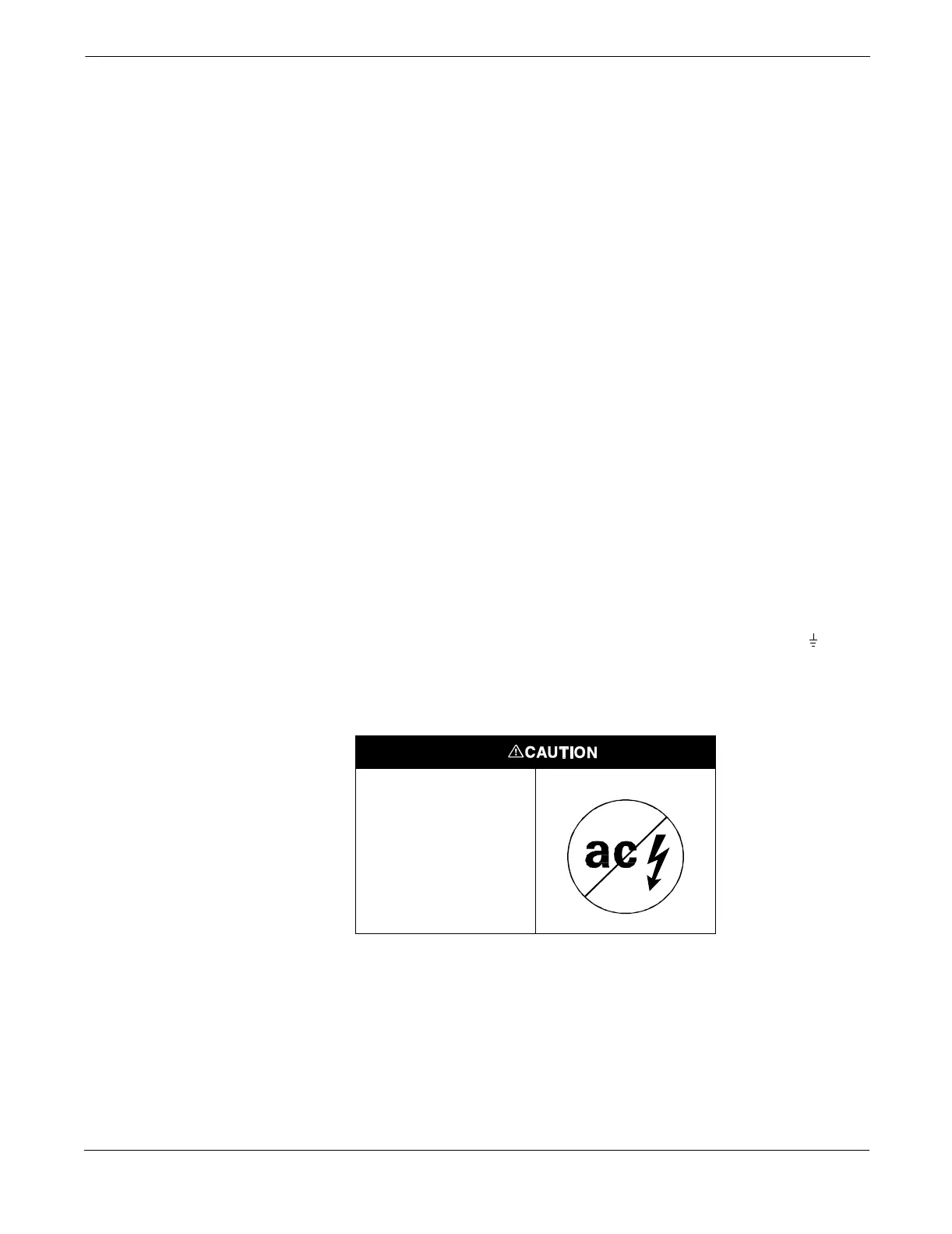
This is a pulsed dc
magneticflowmeter.Do
not connect ac power
to the flowtube or to
terminals1and2of
the transmitter,or
replacement of the
electronics board will
be necessary.