Model 8712C/U/H Magnetic Flowmeter Transmitters
2-2
PRE-INSTALLATION
Before installing the Model 8712C/U/H Magnetic Flowmeter
Transmitter, there are several pre-installation steps that should be
completed to make the installation process easier:
• Identify the options and configurations that apply to
your application
• Set the hardware switches if necessary
• Consider mechanical, electrical, and environmental requirements
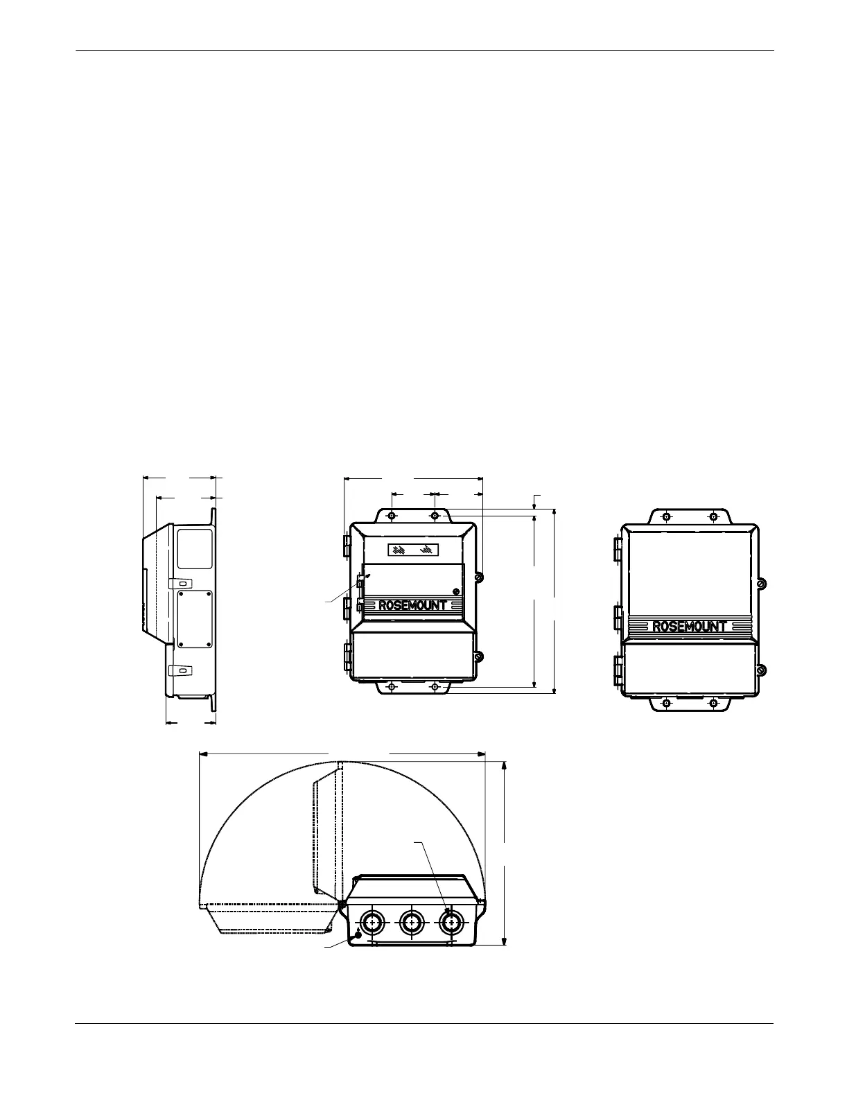
Mechanical Considerations
The mounting site for the Model 8712C/U/H transmitter should provide
enough room for secure mounting, easy access to conduit ports, full
opening of the transmitter covers, and easy readability of the LOI
screen (see Figure 2-1). The transmitter should be mounted in an
upright position.
If the Model 8712C/U/H is mounted separately from the flowtube, it
is not subject to limitations that might apply to the flowtube. For
considerations regarding the installation of the flowtube, please
refer to the flowtube manual (document number 00809-0100-4727).
FIGURE 2-1. Model 8712C/U/H Dimensional Drawing
4.31
(109)
LOI Cover
Standard
Cover
LOI Keypad
Cover
3.51
(89)
9.01
(229)
11.15
(283)
2.81
(71)
3.11
(79)
12.02
(305)
0.44
(11)
17.70 (450)
11.37
(289)
Ground Lug
¾–14 NPT
Conduit
Connection
(3 places)
With LOI Cover
With Standard
Cover
NOTE
Dimensions are in
inches (millimeters).
8712-12A01A, 8712B01A, 8712C01A, 8712D01A
2.96
(75)