d04927.fm
INSTALLATION MANUAL
BRP-Powertrain
Effectivity: 912 Series
Edition 2/Rev. 0
79-00-00
page 11
August 01/2012
2) Connecting sizes and position of connections
General note
NOTE: The oil line connections are optionally available as UNF
threads (AN-8).
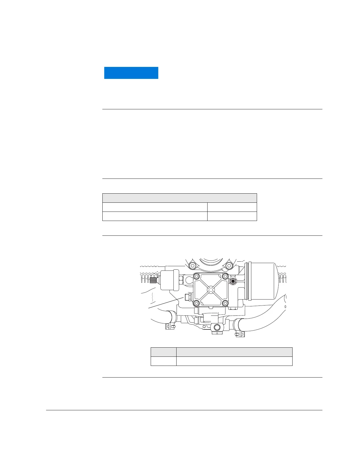
2.1) Oil circuit (engine)
General note See Fig. 5.
Depending on engine configuration, the oil feed line connectors may
vary:
- 912 A/F/S: Thread M18 - optional UNF-thread (AN-8)
- 912 UL/ULS: Inlet nipple - optional M18 or UNF-thread (AN-8)
Oil pump (inlet) Connection variant 1:
NOTE: Suitable for use of a swivel joint.
Graphic Oil pump-inlet
Fig. 5
09123
Utilize the full slip-on length for all connections. Se-
cure hoses with suitable screw clamps or crimp con-
nections..
Oil pump (inlet)
Thread M18x1,5x11
Tightening torque of inlet line 25 Nm (18.5 ft.lb)
Part Function
1 Oil pump (inlet)

 Loading...


