d04921.fm
INSTALLATION MANUAL
BRP-Powertrain
Effectivity: 912 Series
Edition 2/Rev. 0
61-00-00
page 3
August 01/2012
1) Propeller drive
General note The propeller in tractor or pusher arrangement must be fitted on the pro-
peller flange in accordance with applicable regulations. As required utilize
one of the three possible pitch circle diameters (P.C.D) on the flange.
The propeller design must be certified in accordance with applicable reg-
ulations, such as FAR or EASA, by the aircraft manufacturer.
1.1) Technical data
Direction of rota-
tion
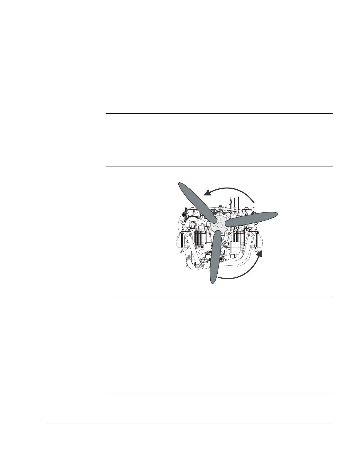
See Fig. 1.
Direction of rotation of the propeller flange:
- left, counter clockwise, looking towards face of flange.
Graphic Direction of rotation
Fig. 1
08629
Transmission Gear transmission:
- i= 2.2727 (50 Teeth/22 T)
- i= 2.4286 (51 Teeth/21 T)
.
Vibration analy-
sis
NOTE: Vibration analysis of the whole system (engine, suspen-
sion, propeller etc.) should be carried out as part of the
certification process.
If no limits are available in the technical literature, a max.
of 1.0 IPS (inches per second) at 5000 rpm. can be as-
sumed.
.

 Loading...


