d04920.fm
INSTALLATION MANUAL
BRP-Powertrain
Effectivity: 912 Series
Edition 2/Rev. 0
24-00-00
page 14
August 01/2012
Graphic
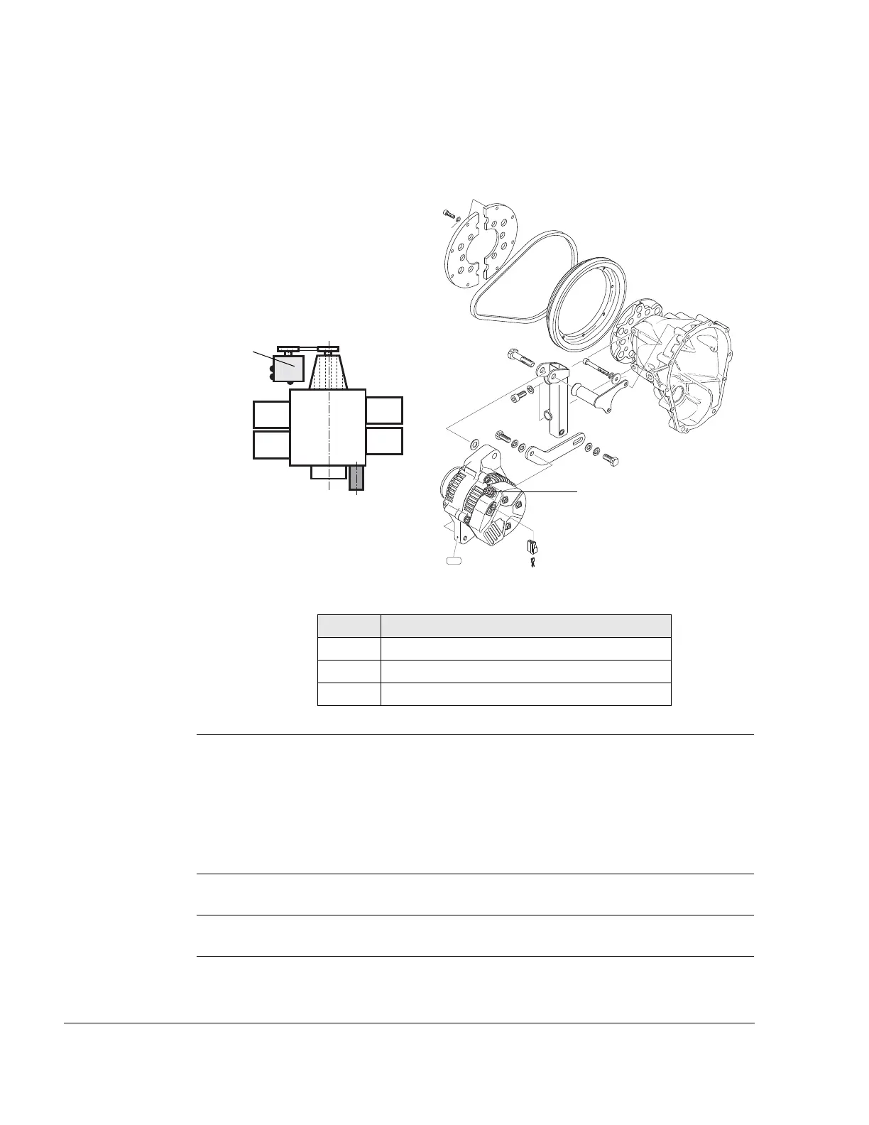
External alternator
Fig. 7
03199,02764,00547
2.6) Requirements for correct operation of the integrated rectifier regu-
lator
Fuse The rectifier regulator must be protected by a slow blowing fuse or circuit
breaker. Fuse or circuit breaker rating must be determined by load, wire
size and length.
Cross section Wire size of the main circuit at least 4 mm
2
(0.006 in
2
).
Capacitor A capacitor of at least 22000 µF/25 V is necessary to flatten voltage.
Teil Funktion
1 External alternator
2 Positive terminal
3 Control wiring
IG
L
B
Cyl. 1
Cyl. 3
Cyl. 2
Cyl. 4

 Loading...


