d04923.fm
INSTALLATION MANUAL
BRP-Powertrain
Effectivity: 912 Series
Edition 2/Rev. 0
73-00-00
page 15
August 01/2012
2.2) Connections for Bowden cable actuation and permissible load
General note See Fig. 8.
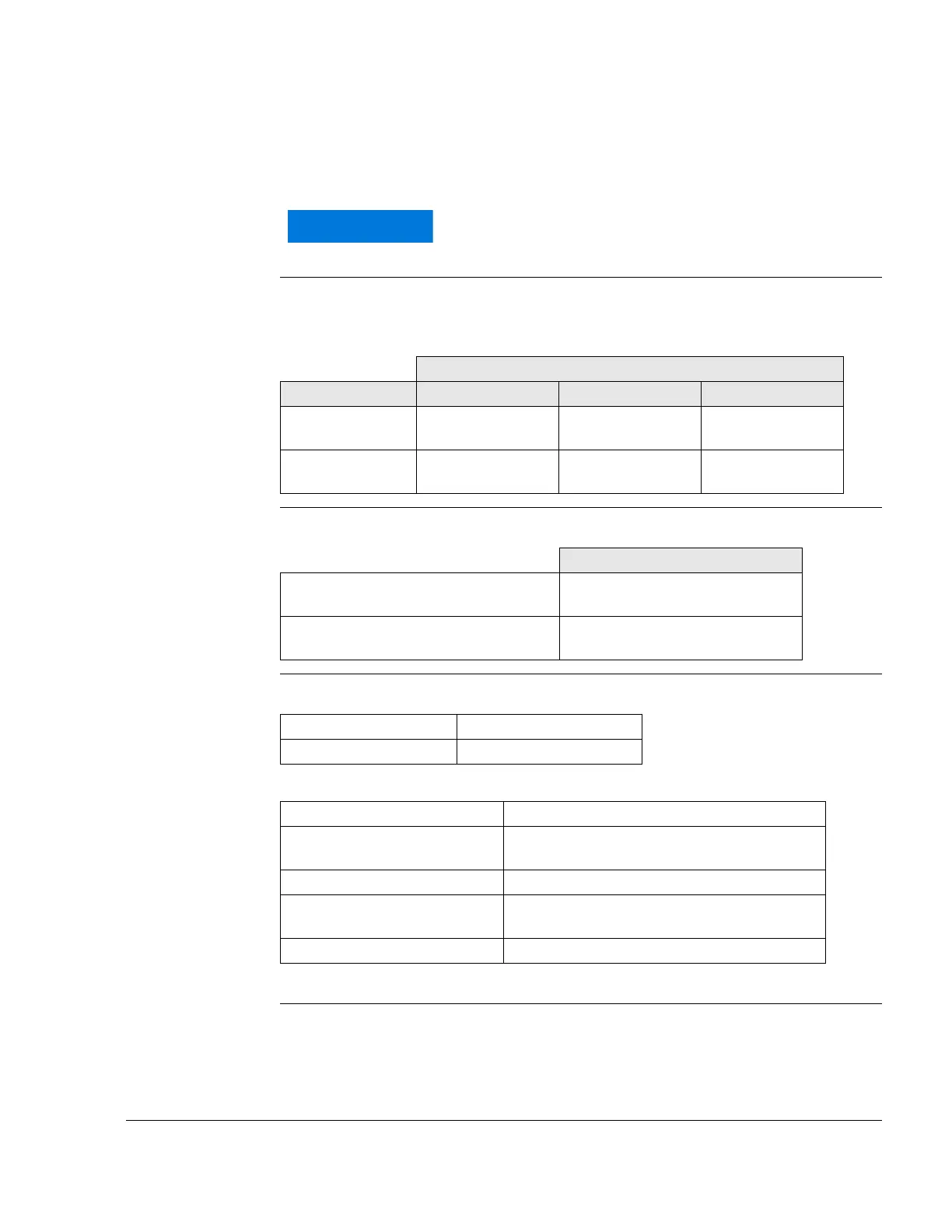
2.2.1) Technical data
Coordinates P1 Centre position of carburetor socket (P1) of the respective carburetor:
Reference point
P2
Limit load on point of reference P2:
Connection Connection (1) for air filter or intake silencer:
Connection (2) for throttle actuation:
NOTE: Throttle opens by spring.
The specified permissible loads must never be
exceeded!
Coordinates P1 [mm]
Carburetor for x-axis y-axis z-axis
Cylinder 1/3 -521 mm
(-20.52 in.)
-180 mm
(-7.1 in.)
25 mm
(0.988 in.)
Cylinder 2/4 -553 mm
(-21.772 in.)
180 mm
(7.1 in.)
25 mm
(0.988 in.)
Reference point P2
Max. allowable forces (limit load) in (N)
in x, y and z-axis
60 N (44 ft.lb)
Max. allowable bending moments (limit
load) in (Nm) in x, y and z-axis
4 Nm (3.32 lb ft)
Outside dia. 50 mm (2 in.)
Slip-on length 12 mm (.47 in.)
Connection on throttle lever Set screw M5x12
Tightening torque 4 Nm (3.32 lb ft) (suitable for 1.5 mm (.06 in.)
steel wire).
Action travel 65 mm (2.56 in.)
Actuating force Min. 1.5 N (.3 lb)
Max. 8 N (1.8 lb)
Limit load 20 N (4.5 lb-force)

 Loading...


