d04923.fm
INSTALLATION MANUAL
BRP-Powertrain
Effectivity: 912 Series
Edition 2/Rev. 0
73-00-00
page 16
August 01/2012
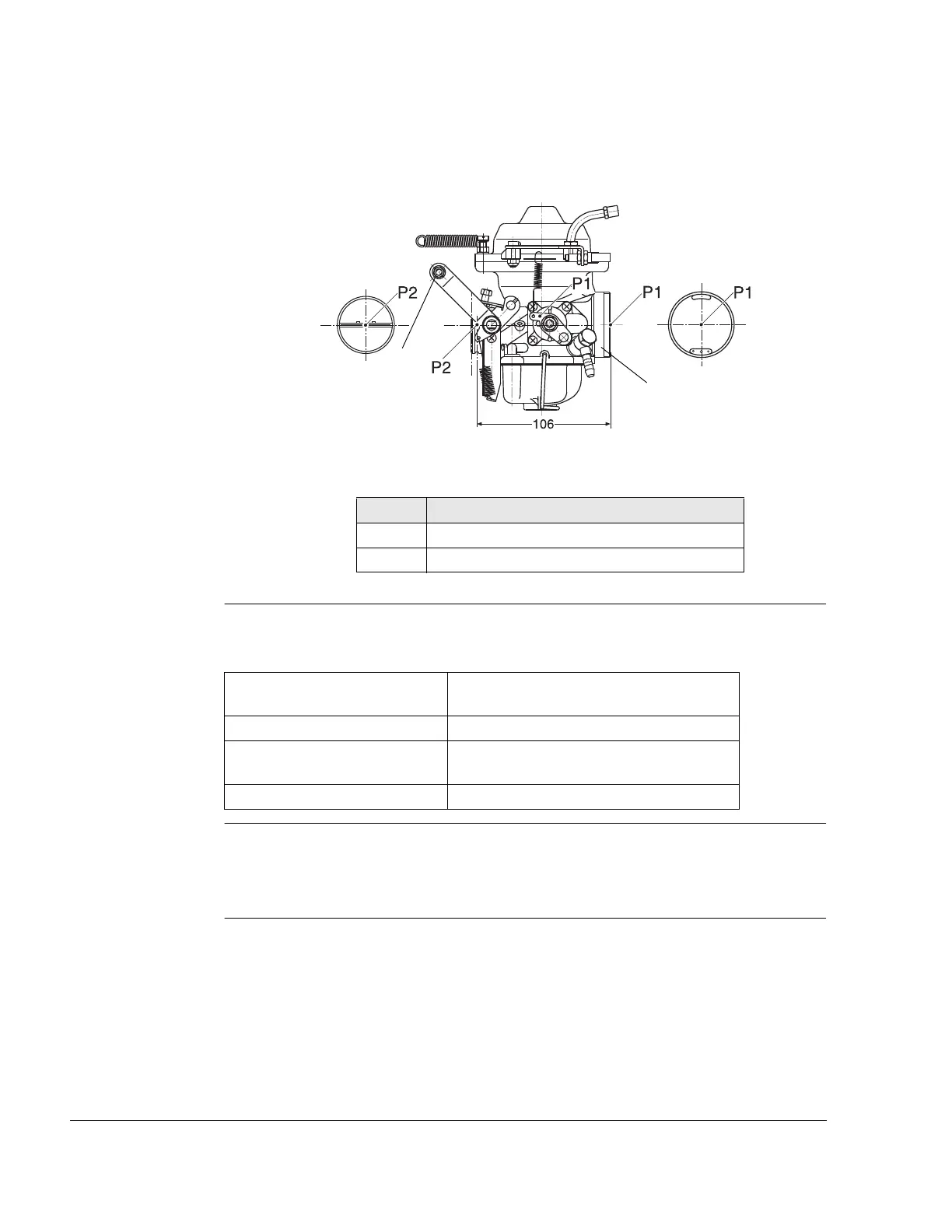
Graphic
Coordinates P1 and Reference point P2
Fig. 8 08339
Starting carb See Fig. 9.
Connection for starting carb (choke) actuation (1):
Directive for choke actuation:
The choke shaft (1) is marked (2). This mark has to point towards cable
engagement (3).
Part Function
1 Connection for air filter or intake silencer
2 Connection for throttle actuation
Connection on choke lever Clamping nippel 6 (suitable for 1.5 mm
(.06 in.) steel wire).
Action travel 23 mm (15/16‘‘)
Actuating force Min. 10 N (2.2 lb)
Max. 45 N (10 lb)
Limit load 100 N (22 lb)

 Loading...


