d04923.fm
INSTALLATION MANUAL
BRP-Powertrain
Effectivity: 912 Series
Edition 2/Rev. 0
73-00-00
page 8
August 01/2012
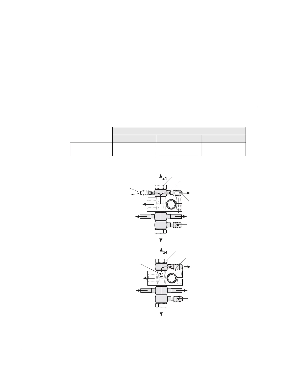
Connection nip-
ple
NOTE: The connection nipple (5) is furnished with an orifice (6)
(0.35 mm = 0.014 in.) essential for operation of the fuel
system.
If the pressure gauge connection (2) is not used and a
hose nipple (7) installed, the banjo bolt assy. (4) marked
with a colour dot or marked “FUEL“ is furnished with an
orifice (8) (0.35 mm = 0.014 in.). This is essential for op-
eration of the fuel system as it prevent a loss in fuel pres-
sure.
Coordinates Position of z4 axis of the fuel manifold:
NOTE: Dimensions always from point of reference (P).
Graphic Fuel manifold
Coordinates [mm]
x-axis y-axis z-axis
Fuel manifold -385.0 mm
(-15.16 in.)
-50.0 mm
(-1.97 in.)
approx 110 mm
(4.33 in.)
fuel pressure sensor
connection
to fuel pressure gauge
to carburetor
to carburetor
from fuel pump
to fuel tank
from fuel pump
to carburetor
to carburetor
fuel pressure sensor
connection
to fuel tank
8
4
7
1
9
4
5
6
1
2
3

 Loading...


