d04920.fm
INSTALLATION MANUAL
BRP-Powertrain
Effectivity: 912 Series
Edition 2/Rev. 0
24-00-00
page 9
August 01/2012
2.4) Ignition switches (MAG switch)
Type Two separate, suitable on-off switches (Fig. 11 pos. 15).
Switching volt-
age
Min. 250 V.
Switching cur-
rent
Min. 0.5 A.
2.4.1) Connection
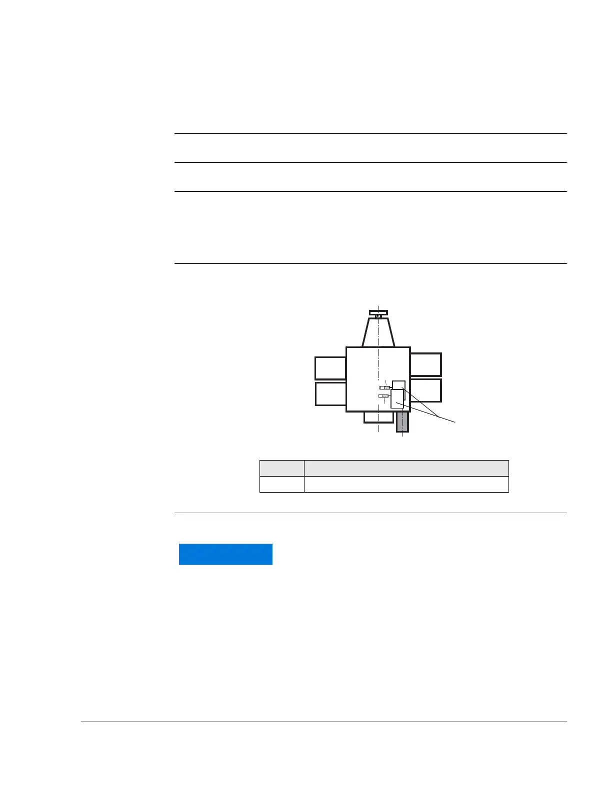
Wires See Fig. 4.
Wires from the ignition switches connect to the electronic module (1).
Graphic Electronic modules
Fig. 4
02501
Wire See Fig. 5.
Part Function
1 Electronic modules
br
br
B
A
Cyl. 1
Cyl. 3
Cyl. 2
Cyl. 4
The electromagnetic compatibility (EMC) and electro-
magnetic interference (EMI) depends essentially on
the wire used.
Min. section area: 2x 0.75 mm
2
(18 AMG) (shielded
flexible cable, shielding braid on both ends grounded
to prevent EMI (e.g. specification MIL-27500/18).

 Loading...


