d04920.fm
INSTALLATION MANUAL
BRP-Powertrain
Effectivity: 912 Series
Edition 2/Rev. 0
24-00-00
page 10
August 01/2012
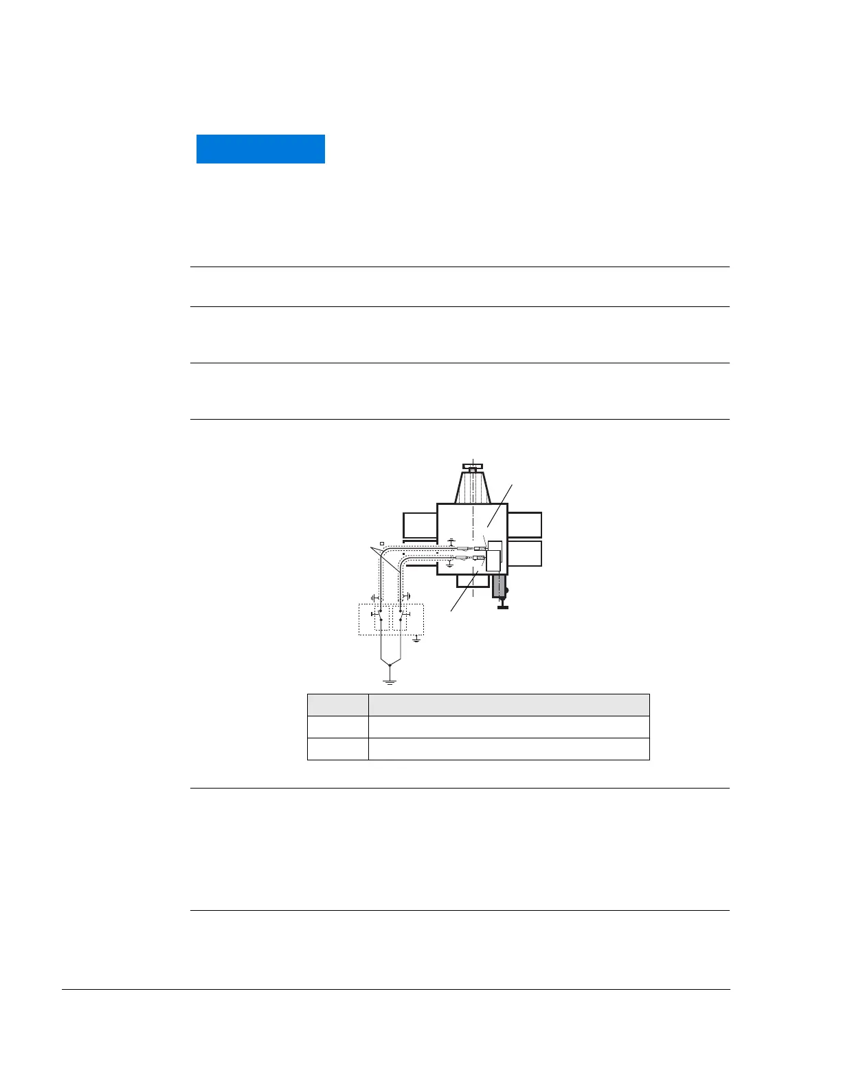
Wire A
Wire of top electronic module (marked “A“) for ignition circuit A.
Wire B Wire of bottom electronic module (marked “B“) for ignition circuit B.
Ignition circuit A NOTE: Ignition circuit A controls: top spark plugs of cylinder 1 and
2; lower spark plugs of cylinder 3 and 4.
Ignition circuit B NOTE: Ignition circuit B controls: top spark plugs of cylinder 3 and
4; lower spark plugs of cylinder 1 and 2.
Graphic Wire
Fig. 5 07602
Flexible wire One each flexible wire 0.75 mm
2
(18 AMG), brown.
Length approx. 35 mm (1 3/8“) beginning at electronic module with one
each plug socket and insulating sleeve 3.96 mm. At the new version the
cable grommet and fasten connector are integrated in the 6-pole connec-
tor housing. See also SI-912-013, latest issue.
No or insufficient shielded cables can cause engine
shut-off due to electromagnetic and radio interference.
The metal base of each ignition switch must be
grounded to aircraft frame to prevent EMI.
Part Function
1 Wire for ignition circuit A
2 Wire for ignition circuit B

 Loading...


