d04921.fm
INSTALLATION MANUAL
BRP-Powertrain
Effectivity: 912 Series
Edition 2/Rev. 0
61-00-00
page 5
August 01/2012
2) Vacuum pump
2.1) Technical data
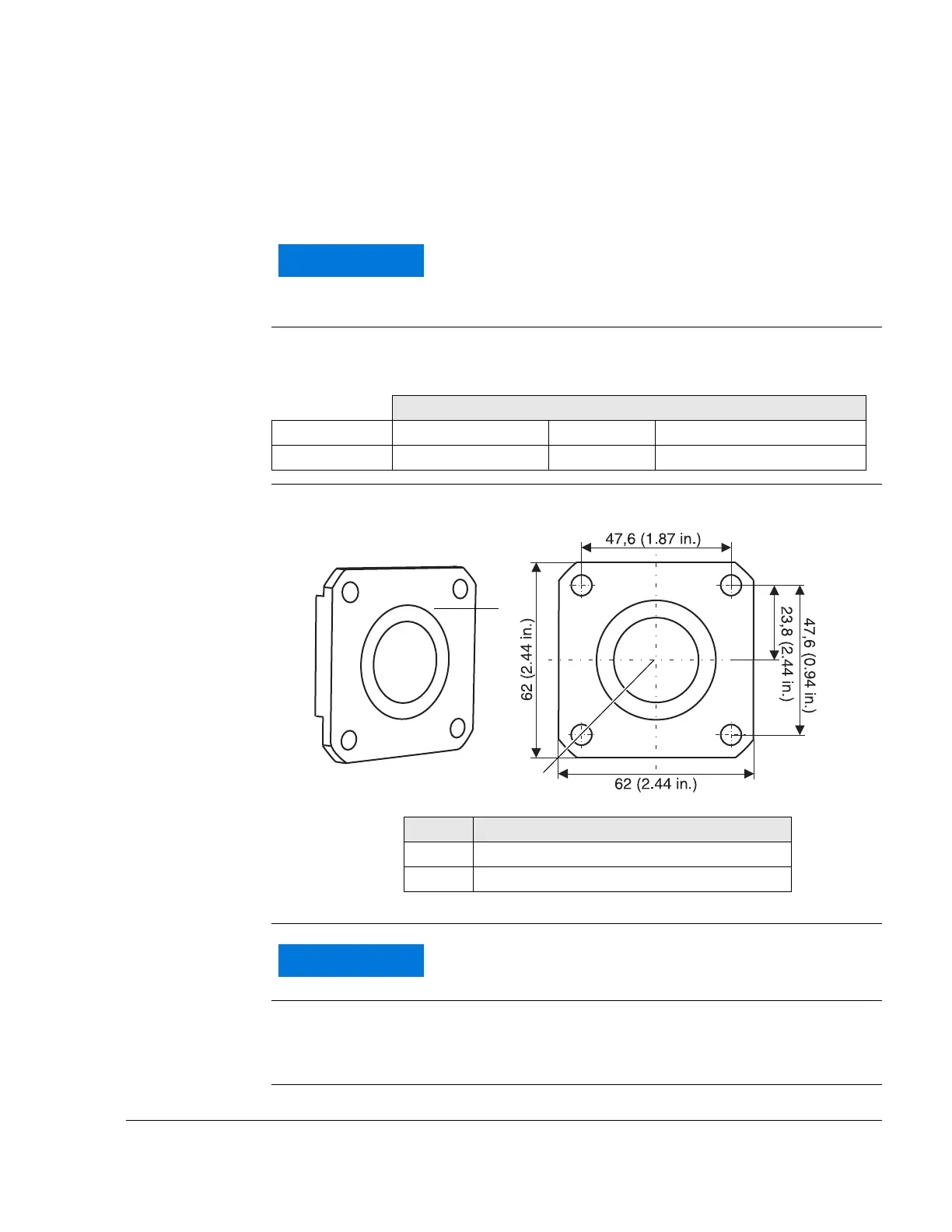
General note See Fig. 3.
Drive Drive via propeller gear.
- Location of the necessary connection (1) on the crankcase.
Graphic Attachment flange
Fig. 3
08322
Connection
Speed reduction NOTE: Speed reduction from crankshaft to hydraulic governor is
1.724 or 1.842, i.e. the vacuum pump runs with 0.58 or 0.54
of engine speed.
Certification to the latest requirements such as FAR or
EASA has to be conducted by the aircraft manufactur-
er.
Coordinates
Connection x-Axis mm y-Axis mm z-Axis mm
-206.3 mm (-8.12 in.) 0 51.5 mm (2.03 in.)
Part Function
1 Connection for Vacuum pump
2 Attachment flange
Pay attention to manufacturers specifications.

 Loading...


