d04919.fm
INSTALLATION MANUAL
BRP-Powertrain
Effectivity: 912 Series
Edition 2/Rev. 0
10-10-00
page 8
August 01/2012
Graphic
Deviation
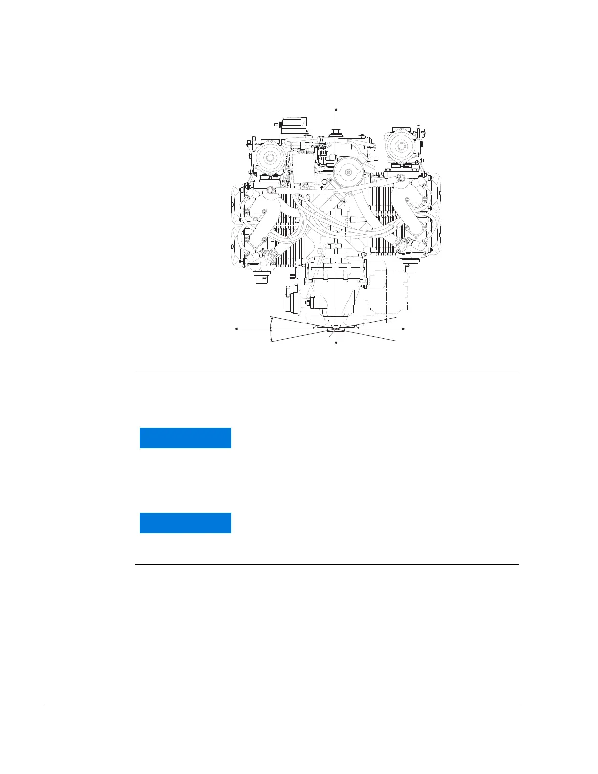
Fig. 2 00515
2.2) Attachment points
General note See Fig. 3.
It is recommended that the 4 stated attachment points R2, L2, R3 and L3
of the engine suspension frame are used.
The hex. screws M10x60 in the attachment points are
for transport only and must not be used for engine
suspension.
A minimum of 4 attachement points must be used.
These must be distributed symmetrically between the
left (L) and right (R) sides.

 Loading...


