d04919.fm
INSTALLATION MANUAL
BRP-Powertrain
Effectivity: 912 Series
Edition 2/Rev. 0
10-10-00
page 7
August 01/2012
NOTE: With suspension on the 4 top lugs L3, R3, L4 and R4 only,
the tilting moment due to the pull of the propeller will be
avoided while, if attached on the bottom lugs only, the mo-
ment of tilting has to be taken care of accordingly.
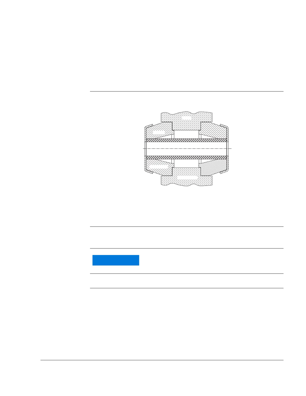
Standard aircraft industry damping elements (e.g. Lord) are suitable. See
Fig. 1.
Graphic Engine suspension
NOTE: The illustration shows Lord J 3608-1 or J 3608-2. rubber
mounts. Consult the manufacturer for the dimensions of
the rubber mounts.
Fig. 1 07600
Vibration neutral-
isation
The vibration and acoustic insulation factor is dependent on the cell man-
ufacturer. Perform the determination as described in SL-912-010.
Damping ele-
ments
Vertical axis The y-axis must be perpendicular to the longitudinal axis of the aircraft.
Deviation Permissible deviation from perpendicular: 10°.
See Fig. 2.
Stützscheibe
Zelle
Gummi
distance tube
support washer
shock mount
Distanzrohr
airframe mount
All elements for neutralising vibrations must be cap-
tive.

 Loading...


