d04925.fm
INSTALLATION MANUAL
BRP-Powertrain
Effectivity: 912 Series
Edition 2/Rev. 0
76-00-00
page 4
August 01/2012
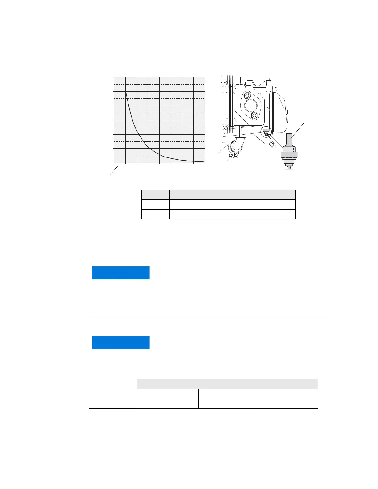
Graphic
Sensor for cylinder head temperature
Fig. 1 00227, 00327
1.2) Sensor for oil temperature
General note See Fig. 2.
BRP-Powertrain offers a non-certified temperature indicating instrument.
Refer to Illustrated Parts Catalog, latest issue.
Marking Marking (2): Marked with “TO“ (Temperature Oel) on oil pump flange.
Position Position of the temperature sensor (1) on the oil pump flange:
Part Function
1 Sensor for cylinder head temperature
2 Graph resistance over temperature
12010080604020 140 160
1200
1000
(Ω)
(°C)
800
600
400
200
0
Certification to the latest requirements such as FAR of
EASA has to be conducted by the aircraft manufactur-
er.
To avoid any mix-up with indication wiring, mark this
particular cable also with “TO“.
Axes
Point of support x-axis y-axis z-axis
-115.0 mm (-4.53 in) 46.0 mm (1.81 in) -150.0 mm (-5.92 in)

 Loading...


