d04925.fm
INSTALLATION MANUAL
BRP-Powertrain
Effectivity: 912 Series
Edition 2/Rev. 0
76-00-00
page 5
August 01/2012
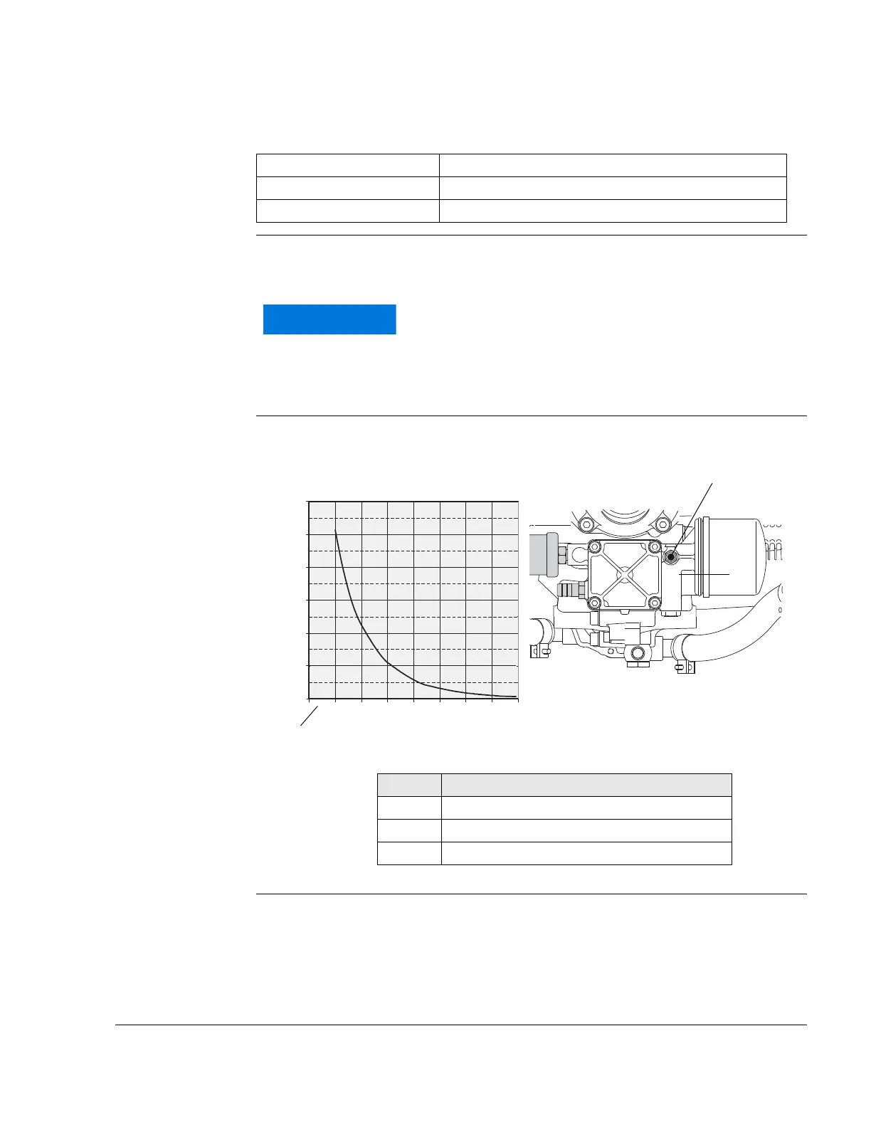
Technical data
Anschlüsse für Öltemperaturgeber:
Graph resistance Graph of sensor resistance over temperature:
See Fig. 2.
Graphic Sensor for oil temperature
Fig. 2
00227, 00327
Location Oil pump housing
Connection of sensor wiring Spade terminal 6.3x0.8 DIN 46247
Grounding Via engine block
The graph resistance over temperature has been de-
termined, and is effective at the following conditions
only:
Ambient temperature: 20 °C (68 °F)
Tolerance: Max ±10 %
Part Function
1 Sensor for oil temperature
2TO marking
3 Graph resistance over temperature
12010080604020 140 160
1200
1000
(Ω)
(°C)
800
600
400
200
0

 Loading...


