EasyManuals Logo

Rotax 912 Series Installation Manual

Rotax 912 Series
199 pages
To Next Page IconTo Next Page
To Previous Page IconTo Previous Page
Page #175 background imageLoading...
Page #175 background image
d04927.fm
INSTALLATION MANUAL
BRP-Powertrain
Effectivity: 912 Series
Edition 2/Rev. 0
79-00-00
page 15
August 01/2012
2.2) Oil tank
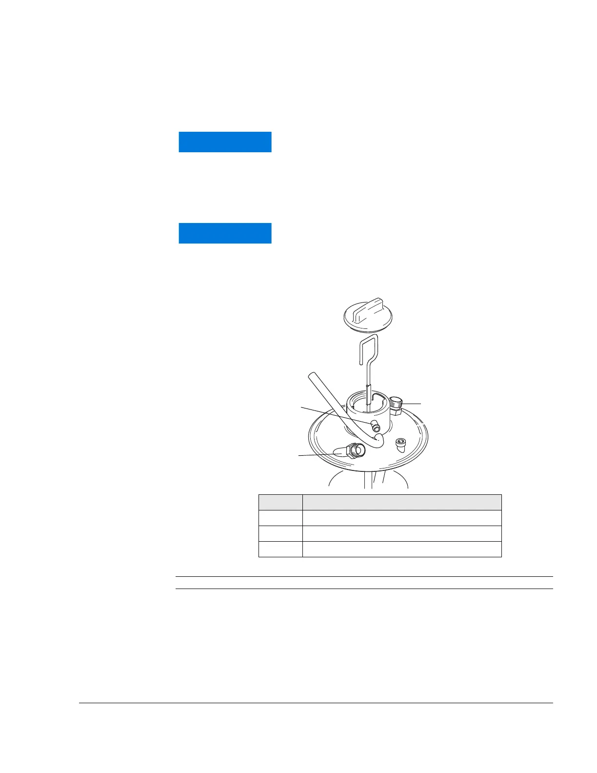
Connection See Fig. 9 and Fig. 10.
NOTE: Optional extra:
Nipple either straight or with 90° elbow. Metric M18x1.5 or
UNF 3/4-16 thread
Connections for oil circuit (engine)
Graphic
Fig. 9 08246
WARNUNG
NOTICE
Only use the oil tank provided in the scope of delivery,
as its design has changed compared with older tanks.
WARNUNG
NOTICE
Check what type of thread or connection there is on
the supplied oil tank.
Part Function
1 Oil feed line
2 Oil outlet
3 Purging nipple
IN
O
U
T
2
1
3

Table of Contents

Other manuals for Rotax 912 Series

Questions and Answers:

Question and Answer IconNeed help?

Do you have a question about the Rotax 912 Series and is the answer not in the manual?

Rotax 912 Series Specifications

General IconGeneral
Redline5800 rpm
TBO2000 hours
Displacement1211 cc
Bore79.5 mm
Stroke61 mm
Power Output80 hp (59.6 kW)
Compression Ratio9.0:1
Fuel TypeAvgas 100LL
Ignition SystemDual electronic ignition
Fuel SystemFuel Injected
Oil SystemDry sump
Engine Type4-cylinder, horizontally opposed, 4-stroke

Related product manuals