d04919.fm
INSTALLATION MANUAL
BRP-Powertrain
Effectivity: 912 Series
Edition 2/Rev. 0
10-10-00
page 12
August 01/2012
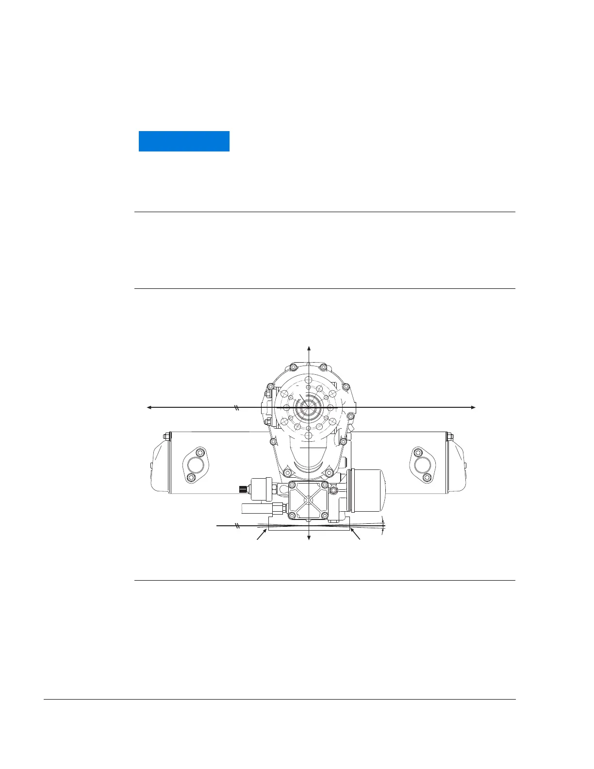
2.4) Permissible installation positions
General note See Fig. 4
NOTE: Dimensions are always from zero reference point and the
coordinate system position remains unchanged.
Installation posi-
tions
The following installation position details refer to the aircraft in
parked position (aircraft on ground, ready for take off).
- Engine suitable for propeller in tractor or pusher arrangement
- Installation only with propeller shaft above cylinders
Propeller axis The centres of attachment points L1 and R1 must be on a y2 axis parallel
to the y-axis.
Permissible deviation from parallelism: 5°
Fig. 4 02454
The oil system, fuel system and the cooling system are
unsuitable for upside-down/inverted installation of the
engine.

 Loading...


