d04923.fm
INSTALLATION MANUAL
BRP-Powertrain
Effectivity: 912 Series
Edition 2/Rev. 0
73-00-00
page 9
August 01/2012
Fig. 4 09192,09139
1.4.2) Fuel pump
General note See Fig. 5.
Slip-on joint Hose connection on fuel pump (1) inlet by slip-on joint.
Fuel intake connection (3):
Fuel outlet connection (4):
Sleeved lines Hose connection on fuel pump (2) supplied with fire sleeved lines.
Fuel intake connection (5):
Fuel outlet connection (6):
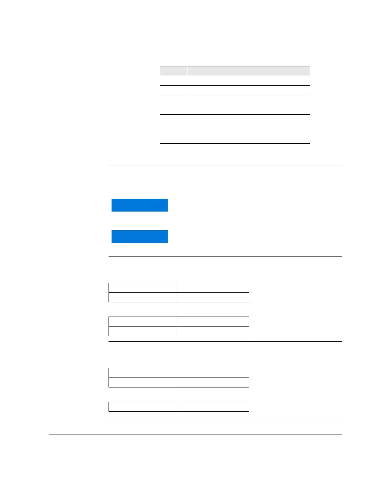
Part Function
1 Fuel manifold
2 Pressure gauge connection
3 Fuel pressure switch connection
4 Banjo bolt
5 Connection nipple
6 Orifice (0.35 mm = 0.014 in.)
7 Hose nipple
8 Orifice (0.35 mm = 0.014 in.)
Ensure at installation of the supply line to fuel pump
that no additional moments or load will rest on the
pump!
Utilize max. slip on length. Secure hoses with suitable
screw clamps or crimp.
Outside dia. 9 mm (.35 in.)
Slip-on length Max. 24 mm (.95 in.)
Outside dia. 6 mm (.24 in.)
Slip-on length Max. 24 mm (.95 in.)
Fitting (8) 9/16-18 UNF (AN-6)
Tightening torque 15 Nm (135 in.lb)
Hose nipple (7) 3/4 DIN 7642

 Loading...


