d04923.fm
INSTALLATION MANUAL
BRP-Powertrain
Effectivity: 912 Series
Edition 2/Rev. 0
73-00-00
page 12
August 01/2012
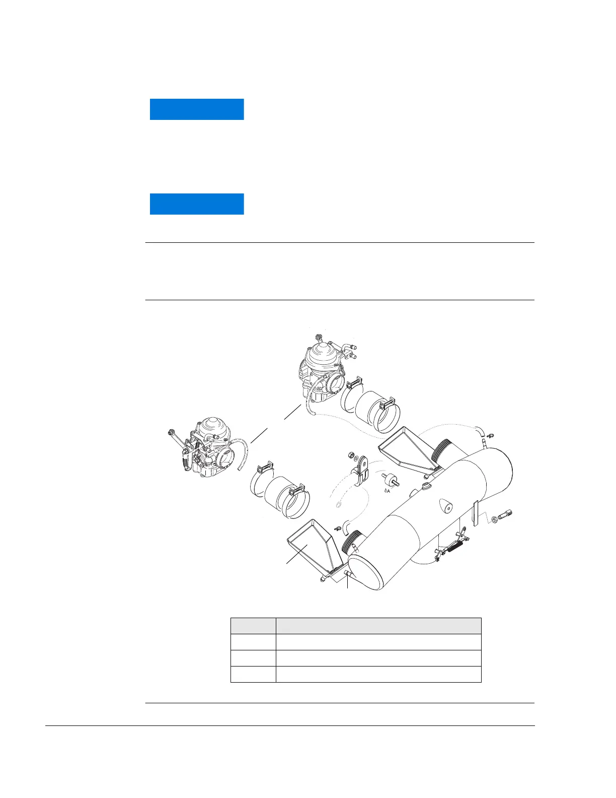
Drip tray The carburetors are positioned above the exhaust sockets. Below the
carburetors one each drip tray (2) with a draining connection (3) is fitted
which serves as a heat shield as well.
Graphic Drip tray and draining connection
Fig. 7 08644
The float chamber venting lines (1) lines have to be
routed into a ram-air and vacuum free zone or into the
airbox, according to the requirements and release of
BRP-Powertrain. See chapter “air intake system“.
These lines must not be routed into the slipstream or
down the firewall.
Pressure differences between intake pressure and
pressure in the carburetor chambers may lead to
engine malfuction due to incorrect fuel supply.
Part Function
1 Float chamber venting lines
2 Drip tray
3 Draining connection

 Loading...


