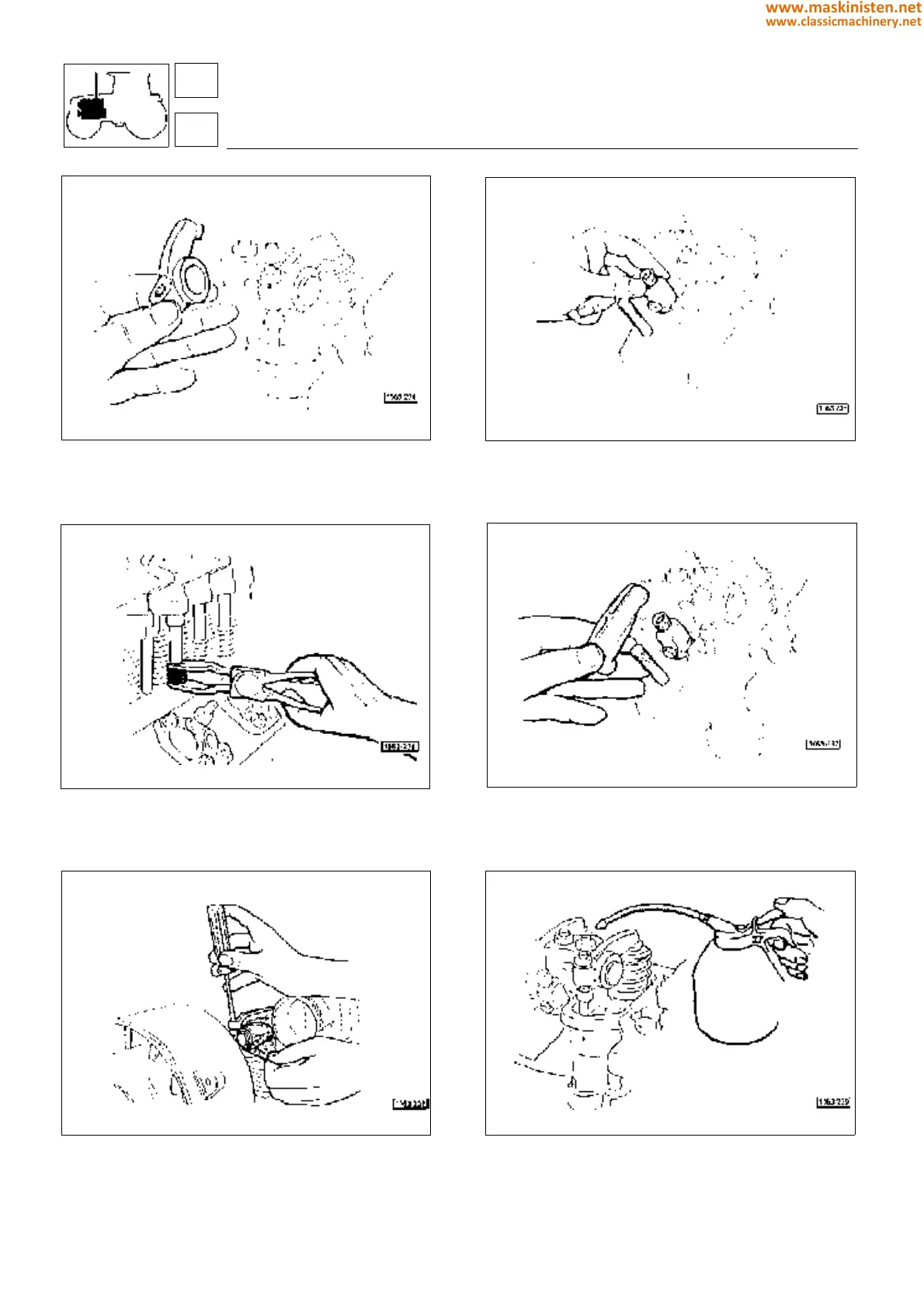
Fig. 59 - Insert the tappet rods, fit the rocker arms and the
rocker arm supports;
Fig. 61 - Using a special tool fit the rod cover pipes and the
positioning springs;
Fig. 63 - Adjust valve and rocker arm clearance;
Fig. 60 - Install the injection nozzles in their seats;
Fig. 62 - Using a plug thoroughly insert the injection nozzles
in their seats orienting the fuel rejection hole towards the
fixing bracket. Install the injection nozzle fixing brackets tigh-
tening the securing screws to the torque specified in the table
on page 90;
Fig. 64 - Oil valve caps and valve springs;
engine
assembly
1
102
www.maskinisten.net
www.classicmachinery.net