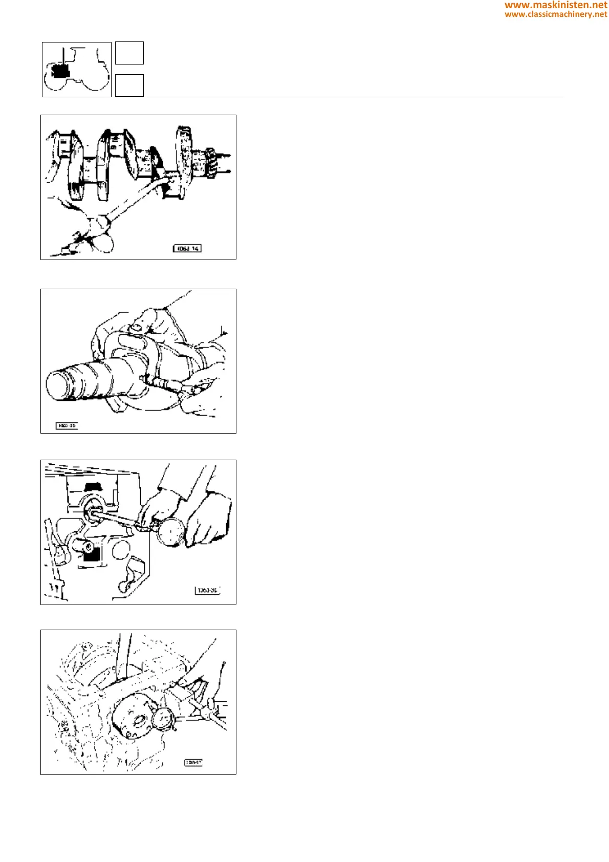
Fig. 13 - Cleaning crankshaft lubricating holes.
Fig. 14 - Checking crankshaft dimensions.
Fig. 15 - Checking main bearing inside diameter.
Fig. 16 - Checking crankshaft end play.
Crankshaft end play is adjusted by two-part spacer rings (see also
specifications table) fitted onto the rear main bearing sides (flywheel side);
these are provided with a projection preventing faulty assembly, the rings
can be mounted after crankshaft installation too.
Each main bearing consists of two shells each being provided with a small
tongue permitting it to be held in position inside the bearing cap seat. The
upper bearing shell is provided with a cavity for oil flow.
Main bearing caps shall be positioned according to the numbering printed
on their bodies and fixed to the block with two special securing screws,
which can only be replaced with other original screws.
Checking crankshaft
After the crankshaft has been thoroughly cleaned examine it carefully.
Meticulously ascertain the main and big end journals do not show signs
of seizure, otherwise rigrinding will be necessary. If the journals are
cracked the crankshaft shall be replaced.
Using a micrometer gauge make sure the main journal diameters are not
below the specifications given in the related table, otherwise a regrinding
should be performed.
Checking crankshaft journal out-of-roundness and
taper
With a micrometer gauge measure crankshaft journal taper and out-of-
roundness amounts; if readings exceed the maximum allowances speci-
fied a regrinding shall be performed. (Refer to specification table).
Checking main bearings
Clean main bearings carefully and then examine the internal surfaces for
indentation, scuffing, scratching or evident antifriction lining wear. If any
replace the main bearings.
Check main bearing inside diameters with an internal comparator. If the
diameters are found in excess of the maximum wear limits, the main
bearings shall be replaced.
Main bearings are supplied as spare parts either with normal size or
undersize inside diameters. The inside diameter undersize range is 0.25
to 0.50 mm.
Be very careful when installing the main bearings in order they can be
correctly positioned. The bearing shells provided with a lubricating hole
must be placed in the upper side (i.e. into the block forging and not into
the main bearing caps).
Mounting main bearing caps
The numbers stamped on the main bearing caps must be on the same
side as those stamped on the block.
Carefully check main bearing cap fixing screws for stretching, if so replace
them with original screws only.
The screws are to be tightened progessively to 1 kgm (9.8 Nm) torque
and subsequently to 3 kgm (30 Nm) torque then using no. 5.9030.640.0
tool furtherly tighten each single screw to an angle of 55°÷1’
engine
crankshaft
12
1
32
www.maskinisten.net
www.classicmachinery.net