controls
electro-hydraulic controls
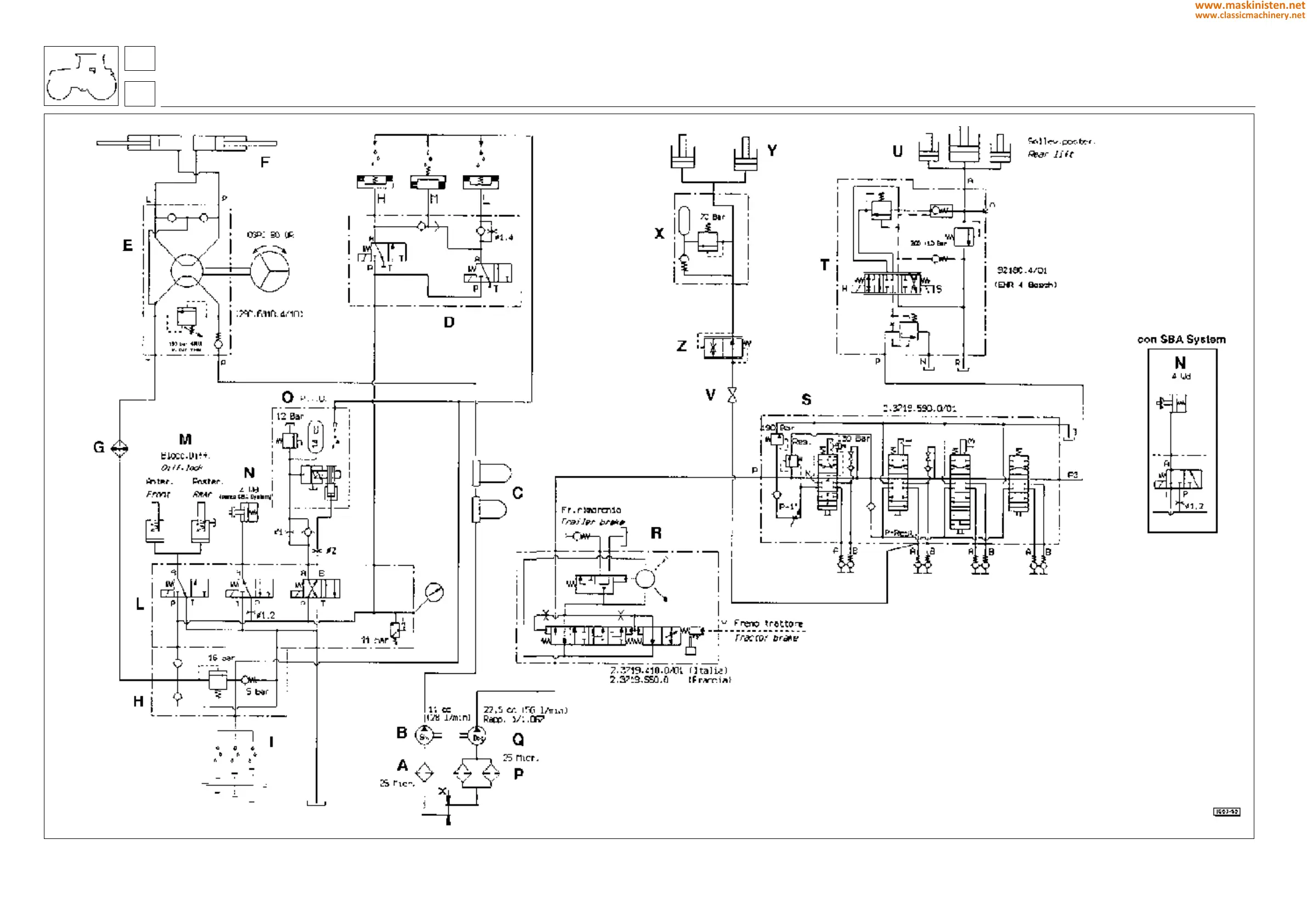
Fig. 7 - Hydraulic circuit diagram for machine equipped with electrohydraulic controls.
6
68
A - oil filter
B - oil pump
C - resonators
D - AGROSHIFT
E - power steering directional control valve
F - steering cylinders
G - heat exchanger
H - pressure control valves assembly
I - transmission lubrication
L - hydraulic power unit
M - differential lock
N - four wheel drive coupler
O - rear P.T.O. clutch
P - oil filters
Q - hydraulic pump
R - hydraulic trailer brake control valve
S - auxiliary spool valve
T - hydraulic circuit for electronic type lift system
U - lift cylinders
V - front lift load holding valve
Y - front lift cylinders
Z - pressure control valve
X - front lift shock valve
320
www.maskinisten.net
www.classicmachinery.net