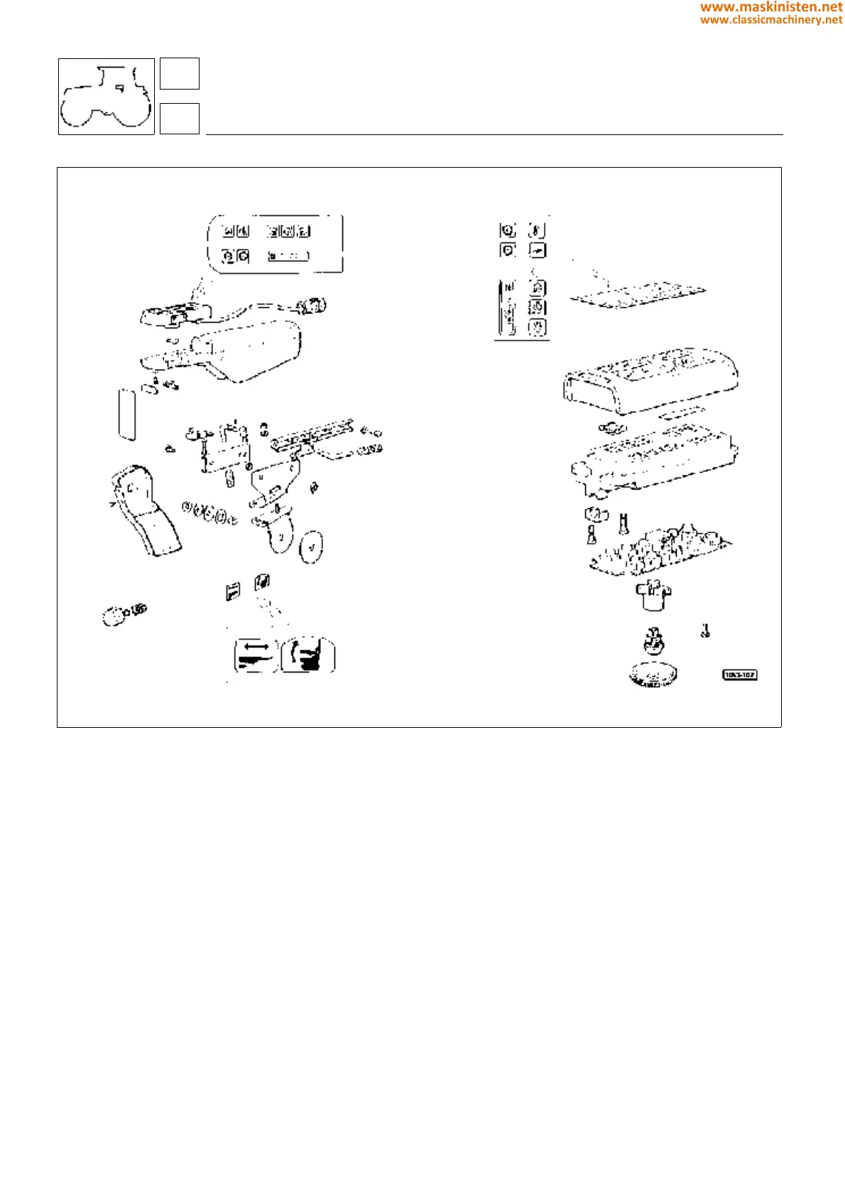
Fig. 3 - Seat armrest and multifunction control handset.
Assembly of seat armrest with multifunction control handset (Fig 4)
Fix the bracket A to the support B, utilizing the washers C and the lock nut D, then torque the nut to 10 Nm (1 kgm
approx).
Fit parts E - F - G and tighten the nut H, so that the lever E allows relative movement between the bracket A and the
support B when in position X and disallows movement when the lever is in position Y.
Fitting the multifunction control handset to the armrest (Fig 4)
Fit the outer section L to the bracket N by means of the screws M. Offer the inner section O to the outer section L,
positioning it in the intermediate longitudinal part. Secure both sections to the armrest P together with the spacer Q
by means of the screws R, having first smeared the threads with Loctite 242.
Make certain that the cable S is positioned correctly as indicated in fig 4.
Fitting the armrest to the seat (Fig 4)
Fit parts T - U - V - Z - J - W in sequence to the bracket I, which is preassembled with the seat.
Apply a restraining torque of 5 Nm (5 kgm) to the front end of the armrest and tighten the lock nut K to the point at
which the armrest can no longer be turned.
controls
multifunction control unit
68
6
332
www.maskinisten.net
www.classicmachinery.net