Removal
The pump is secured to the tractor by 2 of the 4 bolts holding the
pump assembly together. These two bolts are diagonally opposite.
Having removed the pump from the vehicle, the components are
freed by unscrewing the two remaining bolts which keep the cover
A (see fig 3) clamped to the frame C and the pump body B; this
done, remove the washers and then the cover.
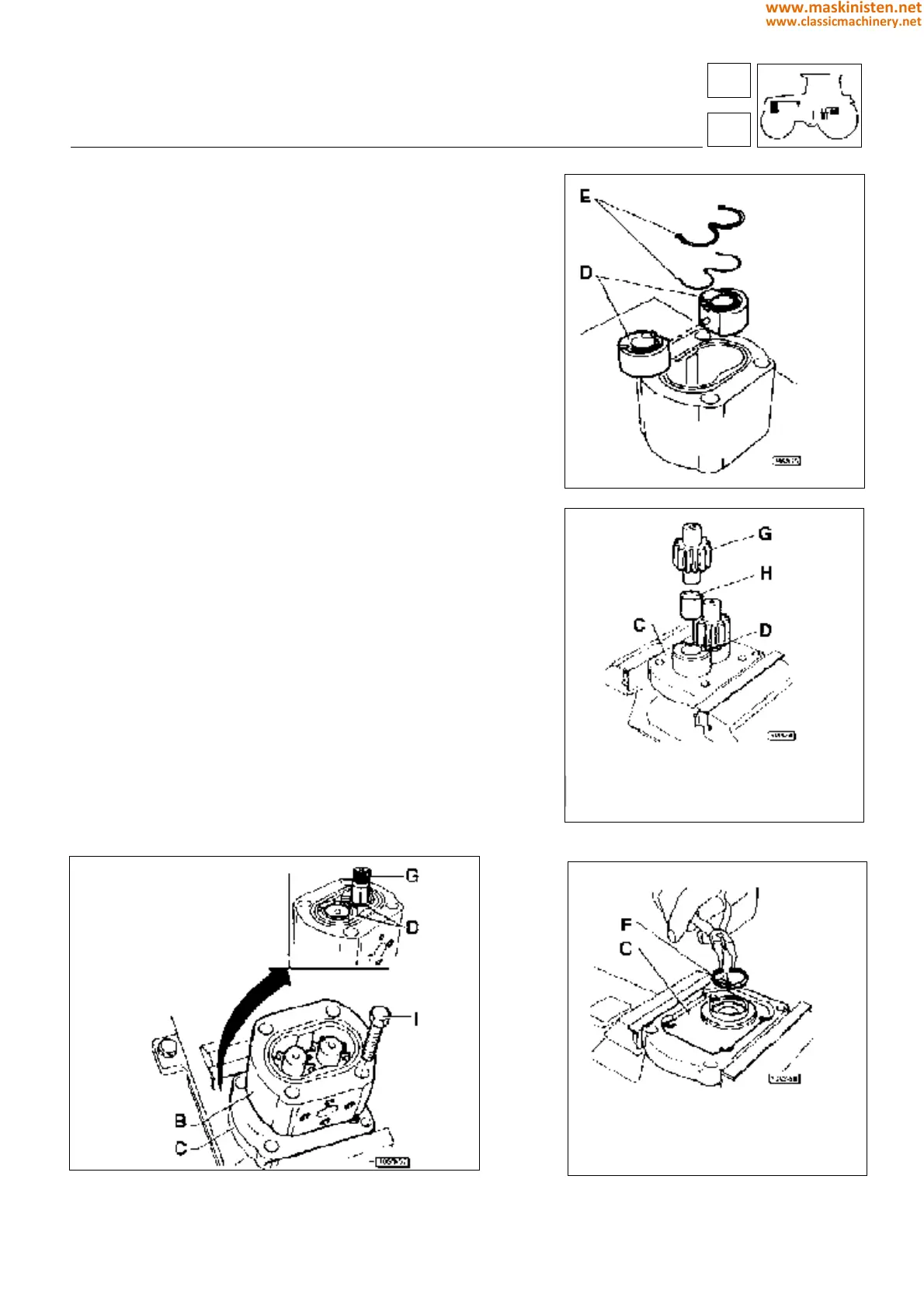
Using a proper pointed tool remove gasket E and then take the
bearings from their seats by pushing from inside outwards and
being careful the connecting pin neither be lost nor damaged.
Mark with a reference the position of the bearings with respect to
the pump case; then remove paying attention the connecting pin
neither be lost nor damaged.
Block the pump case in a vice as shown in figure and then remove
snap ring F.
Remove the seal ring.
WARNING - If pump bearings, pinions or casing are found to be
damaged or worn, these parts cannot be repaired because of their
construction tolerances.
When performing checks, in the warranty period, because of an
oil leakage or an excessive and irregular delivery pressure, only
the gaskets indicated in the spare parts lists can be replaced.
After checking the pump for wear due to abrasion from impurities
and for any other visible damage, when reassembling use, in any
case, a new set of gaskets.
It is also indispensable to mark each single part to reinstall
correctly.
Fig. 5 - Pump disassembly.
Fig. 6 - Internal pump case parts.
Fig. 7 - Pump gears.
Fig. 8 - Snep ring removal.
systems
hydraulic system
D - Bearing
E - Gasket
C - Housing
D - Bearing
G - Gear
H - Bush
C - Base
F - Snap ring
B - Pump case
C - Base
D - Bearings
G - Gears
I - Screw
82
8
379
www.maskinisten.net
www.classicmachinery.net